A body-in-white line runs at a fixed cycle time, but the CMM lab that validates its dimensional quality does not. A quality engineer pulls one panel per hour, walks it to a temperature-controlled room, and waits twelve to twenty minutes for a full report — by which time three hundred more panels have already left the line carrying whatever tolerance drift the sampled part revealed. That gap between when a defect happens and when someone finds out is where scrap, rework, and warranty exposure actually get created, and it is the exact gap that inline gauging integrated with CMM data closes. Manufacturers who still treat CMM as the only source of dimensional truth are inspecting a shrinking fraction of what they build; the plants pulling ahead have connected the reference-grade CMM to a continuous inline measurement layer, and this guide from iFactory's support team walks through exactly how that connection gets made.
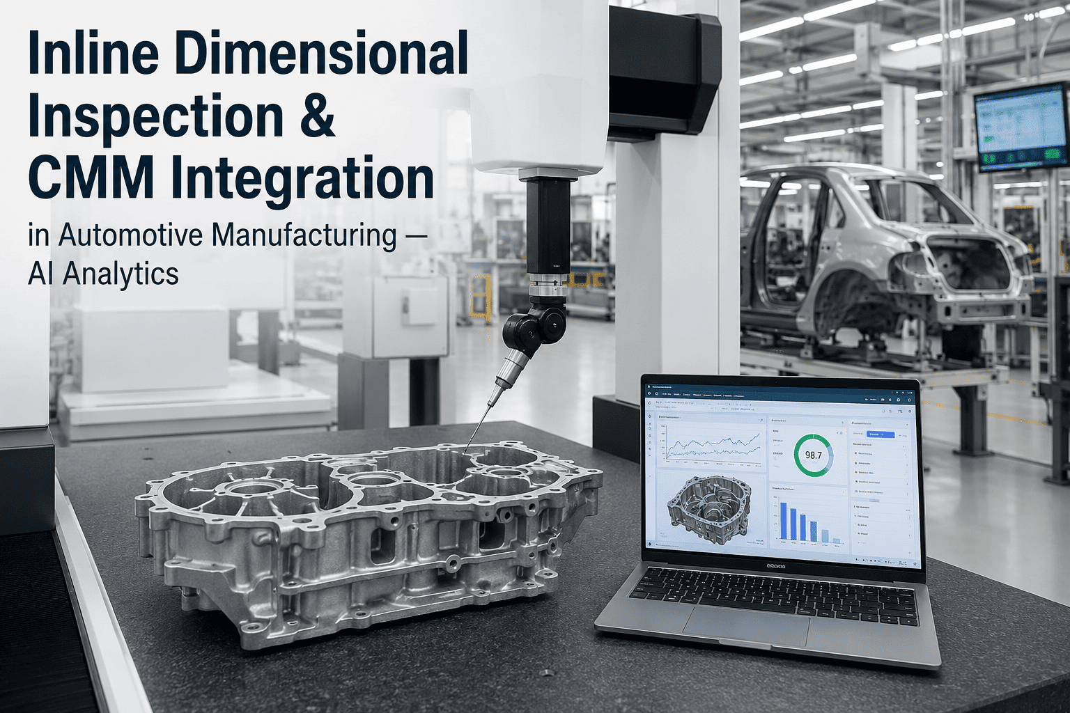
Inline Dimensional Inspection & CMM Integration for Automotive Manufacturing
Sample-based CMM checks were built for an era when 1 part in 200 was good enough. This guide breaks down how AI-driven inline gauging, vision measurement, and CMM data integrate into one dimensional quality system — covering accuracy trade-offs, integration architecture, and what to measure first.
Why Sample-Based CMM Checks Leave Tolerance Drift Undetected
A single stamping die, weld fixture, or robot end-of-arm tool that drifts out of position does not announce itself. It produces parts that are marginally out of tolerance, then further out of tolerance, and the drift compounds silently until someone happens to pull the right part for CMM inspection — or until a downstream assembly problem forces an investigation. Because manual CMM sampling typically covers fewer than twenty features on a handful of parts per shift, the odds of catching an early-stage drift on the specific feature that matters are low, and the odds of catching it before hundreds of parts are affected are lower still.
The economics of this gap are what push plant leaders toward inline measurement. Every hour a dimensional issue runs undetected multiplies the containment cost — parts already welded into a body assembly cannot simply be pulled from a rack, they have to be traced, re-measured, and in the worst case scrapped as sub-assemblies. Inline gauging does not replace the CMM's role as the metrology reference; it closes the detection gap between reference-grade audits by measuring every part, or close to every part, against the same CAD nominal the CMM uses for its own comparison.
CMM, Inline Vision, and Laser Scanning — Where Each One Fits
No single measurement technology covers every dimensional inspection need in an automotive plant. The table below compares the three primary methods on the dimensions that matter for a quality engineering team deciding where to deploy each one.
| Method | Typical Accuracy | Speed | Best Fit |
|---|---|---|---|
| Reference CMM (bridge/gantry) | ±2–5 µm | 12–20 min per part | First-article validation, PPAP submission, audit-grade traceable measurement |
| Portable articulating-arm CMM | ±25–75 µm | 3–8 min per part | On-machine verification, large weldments, field diagnostics without lab access |
| Inline structured-light / stereo vision | ~0.1 mm | Within station cycle time | 100% inline dimensional verification, gap-and-flush, GD&T screening at line speed |
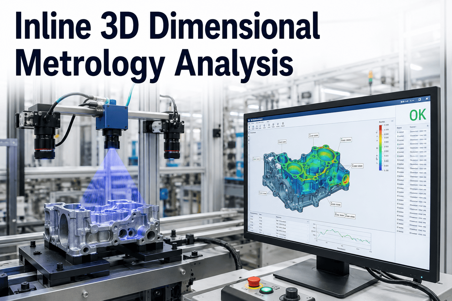
| 3D AI digital-twin alignment | Sub-millimeter, 500+ features | Within station cycle time | Full-body dimensional coverage tied directly to the CAD nominal, tolerance-drift trending |
The pattern most quality organizations converge on is not choosing one method over the others — it is layering them. The CMM remains the traceable reference used for first-article inspection, PPAP, and periodic audits; inline vision and digital-twin alignment carry the 100% coverage burden between those reference checks, and every inline measurement is periodically correlated back against the CMM to confirm the two systems agree.
See Inline Gauging Correlated Against Your CMM Data
iFactory AI connects inline vision measurement, portable CMM data, and reference CMM reports into a single dimensional quality record — so every feature, on every part, traces back to the same CAD nominal.
The Integration Pipeline — From CAD Nominal to Line-Side Decision
Connecting inline gauging to CMM-grade measurement is a data pipeline problem as much as a hardware problem. The nominal geometry has to travel from design through to the point where a camera or probe is comparing a live part against it, and the deviation result has to travel back into the systems where quality engineers and operators actually make decisions.
When a CAD revision changes a feature — a bracket relocation, a new hole pattern — the inspection plan updates from the revised model rather than requiring a multi-week manual re-teach of the vision system, which is one of the biggest operational differences between a modern digital-twin approach and older fixed-gauge or hand-programmed vision setups.
Prioritizing Features — Where Inline Coverage Pays Back Fastest
Gap-and-Flush on Closure Panels
Door, hood, and fender gap-and-flush is both a customer-visible quality metric and a common source of rework. Inline measurement catches drift before hundreds of bodies leave the line with the same offset.
Hole Position and Stud Location
Fastener and stud locations feed directly into downstream assembly. A shifted hole pattern that isn't caught inline surfaces as a fit problem two or three stations later, at higher cost to fix.
Sub-Assembly Flatness and Warpage
Point-cloud analysis detects warpage trends from tooling wear before a part fails final assembly, giving maintenance a lead indicator rather than a reactive breakdown.
Weld Location Verification
Confirming weld position against the CAD-called location, alongside dimensional checks, catches fixture drift that would otherwise only surface in a destructive weld audit.
PPAP and First-Article Features
Critical characteristics tied to customer PPAP submissions stay on the reference CMM, with inline data used to monitor stability between formal submissions.
Safety-Critical Dimensional Callouts
Features tied to occupant safety or structural performance keep the tightest measurement discipline, typically dual-verified by both inline and reference CMM methods.
Industry Perspective on Dimensional Quality Strategy
I used to defend the CMM as the only measurement anyone should trust, and in a lab environment that is still true — nothing beats a bridge CMM for traceable accuracy. What changed my mind was watching how much drift happens in the hours between samples. A fixture that starts walking at 6am can produce four hundred marginal panels before the 10am CMM pull catches it, and by then those panels are welded into bodies. Inline measurement isn't trying to out-accurate the CMM, it's trying to close that four-hour blind spot. The plants doing this well treat the CMM and the inline system as one measurement program, not two competing ones, and they correlate the data constantly so nobody has to argue about which number is right.
Common Questions About CMM and Inline Gauging Integration
Bring Your CMM and Inline Measurement Into One System
iFactory AI integrates CAD-driven inline gauging with your existing CMM program, giving quality engineering one dimensional quality record instead of two disconnected data sets.