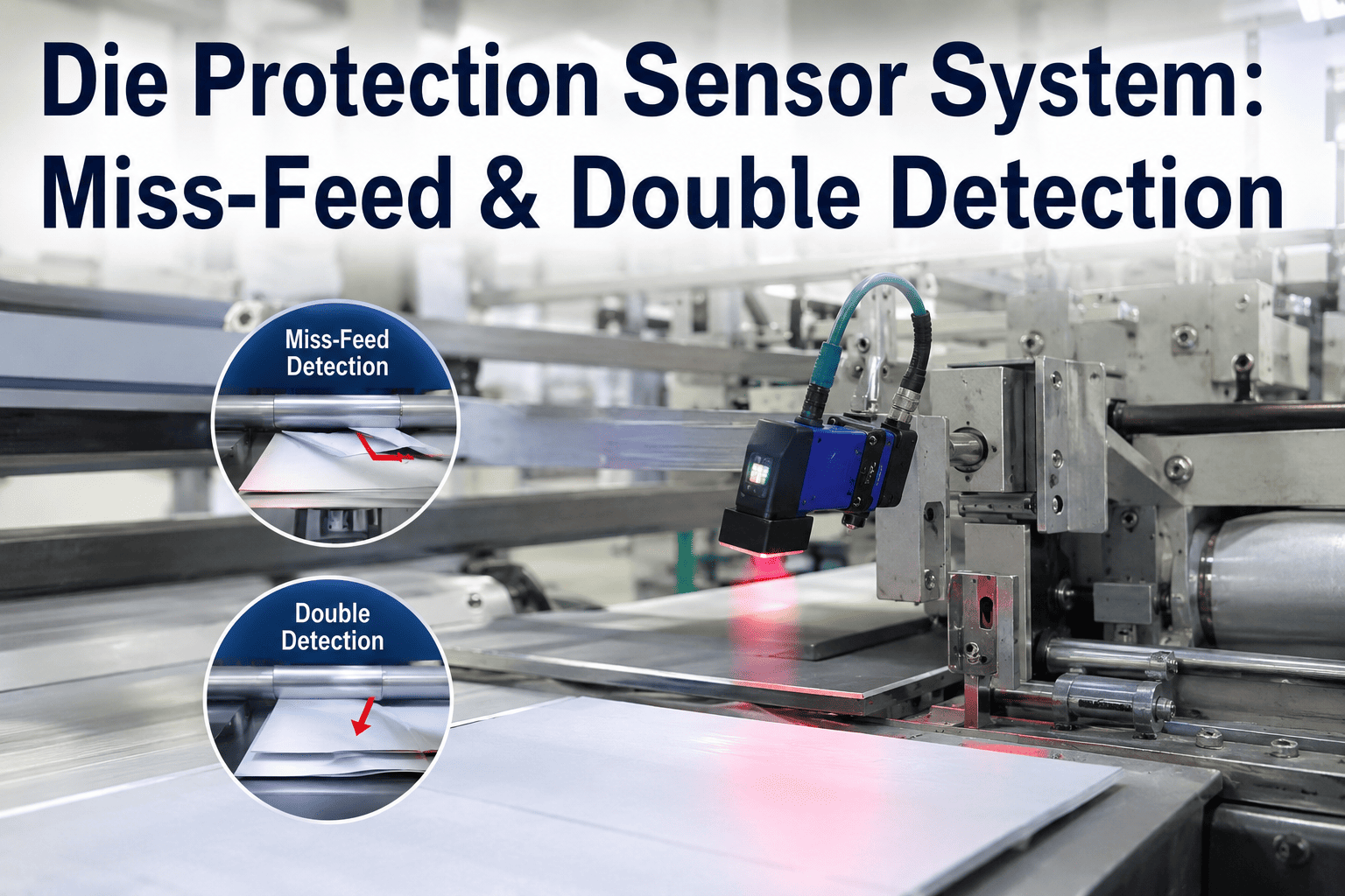
A die crash happens in milliseconds, and by the time an operator hears the sound that means something went wrong, the tooling is already damaged. A miss-feed, a double blank, or a part that failed to eject all look identical from the operator's station until the press closes on material that should not have been there. Die protection sensors exist to catch these conditions during the press cycle, before the ram closes, and stop the stroke automatically rather than relying on a human reaction time that physically cannot beat a press running at production speed. iFactory integrates die protection sensing with connected monitoring and analytics, so every stop is logged, every fault pattern is tracked, and your stamping line's protection system gets smarter instead of just louder. To see this monitoring layer running against your own press data, book a demo.
Stop the Stroke Before the Die Ever Closes on a Problem
iFactory connects die protection sensors to a monitoring layer that catches miss-feeds, double blanks, and part-out failures in real time, logs every stop with cause, and turns nuisance-stop patterns into a tuning signal instead of a mystery.
What Die Protection Sensors Are Actually Watching For
Die protection is often talked about as one category, but it is really three distinct failure modes, each with its own detection challenge and its own consequence if missed. Understanding the difference matters because the right sensor technology and stroke-timing strategy differs across all three.
All three faults share the same underlying risk: the press does not know anything is wrong unless something tells it, and the press cycles fast enough that a human catching the problem by sight or sound is always too late. Die protection sensing exists specifically to close that gap between when the fault occurs and when the press needs to know about it. A stamping operation that has never mapped its historical crash records against these three categories is often surprised to find one fault mode accounts for a disproportionate share of downtime, which is exactly the kind of pattern a properly logged sensor system reveals over time.
Matching Sensor Type to the Fault You Need to Catch
No single sensor technology covers all three fault modes equally well. A properly protected die typically combines several sensor types, each doing the job it is best suited for, rather than relying on one universal sensing approach across the whole tool.
| Sensor Type | Detects | Best Fit | Consideration |
|---|---|---|---|
| Proximity Sensors | Material presence, position, feed length | Miss-feed detection at strip edge or pilot location | Robust and simple, the standard starting point for feed monitoring |
| Pick-to-Light / Photoelectric | Part presence on a chute or in a bin | Part-out confirmation after ejection | Self-adjusting diffuse-mode sensors avoid the need for reflective targets |
| Displacement Sensors | Sub-thousandth-inch die gap deviation | Double blank and pulled slug detection via stripper position | Highest precision, monitors the die height itself rather than the material |
| Mechanical Whisker Switches | Physical obstruction in the feed path | Legacy or low-cost miss-feed backup detection | Durable and simple, but less precise than electronic alternatives |
Displacement-based systems monitoring the separation gap between upper and lower die deserve particular attention because they catch double blanks and pulled slugs indirectly, by detecting that the die itself is not closing to its expected height, rather than trying to directly sense the material stack. This makes them effective against fault conditions that are physically difficult to sense with a simple presence switch. The tradeoff is that displacement sensing requires an adaptive calibration approach to be practical, since a fixed alarm threshold set once at commissioning rarely holds up against the natural variation a real production process exhibits over thousands of strokes.
Get your die protection sensor layout reviewed against your fault history
iFactory maps your press's actual crash history against sensor coverage to find the gaps before the next die crash finds them for you.
Why When a Sensor Fires Matters as Much as What It Detects
A sensor that correctly detects a fault is only useful if it reports that fault early enough in the stroke for the press control system to actually stop before the die closes. This is the timing window problem, and it is a mechanical constraint as much as a sensing one.
This is exactly why sensor placement and press speed interact directly with what fault types are even detectable in a given application. A press running at high strokes per minute has a proportionally shorter detection window, which is part of why displacement-based systems that monitor die gap continuously, rather than only at one discrete check point, have become the preferred approach for high-speed progressive die work.
Sensor mounting location adds a further mechanical constraint to this timing picture. A sensor installed in the upper die is exposed to cable flexing on every single cycle and a meaningfully higher risk of shock damage than one mounted lower in the press structure, and repeated flexing eventually fails that cable regardless of how well the sensor itself performs. When upper-die mounting is unavoidable for a given detection point, running the cable through a die-mounted junction box to a press-mounted interface at least confines the eventual failure to a cable that is easier and faster to replace than rewiring the sensor connection itself.
Why Overly Precise Sensing Can Backfire
It is tempting to assume that more sensitive detection is always better, but die protection has a well-documented failure mode in the opposite direction: sensors tuned to a precision level the production environment cannot actually sustain trigger false stops so often that operators start disabling or ignoring them, which defeats the entire purpose of having protection in place.
The fix is not less sensitivity, it is calibration tuned to the real variance of your specific process rather than a theoretical ideal. A displacement-based system with adaptive learning, which establishes alarm setpoints from actual production data once the press is running at speed, avoids much of this problem by setting limits close to real process variation instead of an arbitrary tight number chosen in the abstract. It is also worth naming plainly that feed detection precision has a practical ceiling worth respecting: a sensor capable of resolving a fraction of a thousandth of an inch sounds impressive, but tuning an alarm to that level of precision when the production process itself naturally varies more than that all but guarantees the sensor spends its life crying wolf.
What Happens After the Sensor Actually Stops the Press
The sensor and the press control loop handle the immediate stop. What happens after that stop is where a connected monitoring layer adds value the sensor system alone cannot provide, turning each individual stop event into part of a larger pattern instead of an isolated inconvenience.
Which Stamping Operations Get the Most Value From Connected Die Protection
Die protection sensing benefits nearly any stamping operation, but the value of connecting it to a monitoring layer scales with a few specific operational characteristics. Recognizing which of these apply to your line helps set realistic expectations for how quickly the investment pays back.
How iFactory Connects Die Protection Into a Monitored System
iFactory does not replace your existing die protection sensors, it connects them to a monitoring and analytics layer that captures every stop event, tracks pattern trends over time, and gives your maintenance and process engineering teams the data to tune calibration correctly instead of guessing.
What Stamping Teams Ask Before Upgrading Die Protection
Turn Every Die Protection Stop Into Data You Can Act On
iFactory connects your existing die protection sensors to a monitoring layer that logs every stop, isolates nuisance triggers from real faults, and flags tooling wear before it becomes a crash.