Aerospace Avionics: Adaptive SPC for Stable Cpk

By Grace on June 16, 2026

aerospace-avionics-adaptive-spc-stable-cpk

Every operations director in aerospace avionics knows the moment when the third false alarm of the shift appears on the control chart. The X-bar point sits above the UCL. The operator flags it. The quality engineer investigates. The conclusion is the same as the last two: the process is fine, the limits are wrong, and the corrective action log records another closed event that changed nothing. The real cost is not the 45 minutes of investigation time. It is the gradual erosion of alert credibility that leaves the one real signal undetected while the team investigates noise. In avionics production, where IPC Class 3 assemblies demand zero defects and AS9100 mandates documented process control, the gap between static control limits and a multi-state manufacturing process is the single largest source of preventable defects, wasted investigation hours, and unplanned Cpk erosion. Adaptive control limits close this gap by replacing static UCL and LCL with dynamic boundaries that recalibrate automatically to every material lot change, solder profile transition, and product variant switch — so the operations director sees alerts only when the process genuinely deviates from its current operating norm, not from the norm that was qualified 12 months ago.

Adaptive Control Limits for Aerospace Avionics Ops Directors
When Static UCL/LCL Generate More False Alarms Than Real Signals, Adaptive Limits Are Not an Upgrade — They Are the Only Way to Sustain Cpk 1.67+ Across Material Lots, Product Variants, and Shift Transitions
iFactory's adaptive control limit platform replaces static UCL/LCL with self-adjusting dynamic boundaries that follow the real process across every material change, solder profile transition, and product variant switch — with ML-driven regime change detection, automated AS9100 limit change logs, and a 60-70% reduction in false alarms that restores operator trust in the control system.
60-70%
False alarm reduction when adaptive ML-controlled limits replace static UCL/LCL — eliminating the alert credibility gap in multi-state avionics production
1.67+
Cpk sustained across product variant transitions when adaptive limits recalibrate automatically — eliminating the quarterly Cpk decay cycle
95%
Of alerts that fire with adaptive limits represent genuine assignable-cause events — operators act because the system has earned credibility back
3-5x
Faster drift detection when adaptive EWMA-based UCL/LCL tighten automatically as the process stabilises — catching drift at half-sigma onset

The Static Limit Trap: Four Failure Modes That Erode Cpk Between Quarterly Studies

Static control limits were designed for a manufacturing environment where raw materials, process settings, and environmental conditions remained stable between capability studies. Aerospace avionics production does not operate in that environment. Every material lot change, solder profile adjustment, thermal cycle, and product variant transition shifts the process distribution. Static limits do not track these shifts. They remain anchored at the qualification baseline while the real process moves around them — producing false alarms, missed signals, and a Cpk that drifts silently between quarterly reports.

Material Lot
Transitions
Every new solder paste batch, component reel, or PCB substrate lot shifts the process mean and variance. Static limits cannot distinguish this common-cause shift from an assignable-cause event — producing 15-25 false alarms per lot transition.
Static: 15-25 false alarms
per lot transition
Adaptive: Limits recalibrate
within transition window
Product Variant
Changeovers
Switching between avionics product variants with different component densities, solder profiles, and IPC Class 3 acceptance criteria shifts the entire specification range. Static limits calibrated for the previous variant generate false alarms on the new variant's normal variation.
Static: 25-45 min manual
recalibration per change
Adaptive: Automatic limit set
transition in milliseconds
Thermal Cycle &
Equipment Drift
Reflow oven temperature zones drift with component aging, ambient temperature shifts, and conveyor load variation. A 2-degree drift in zone 3 is invisible to static limits until solder joint quality degrades — by which time 40-60 boards have passed through the shifted profile.
Static: 40-60 boards produced
before drift is detected
Adaptive: Drift flagged at
half-sigma onset
Operator &
Shift Variation
Different operators apply paste with different pressure profiles. First shift runs at higher line speed than third shift. Static limits treat all shifts as the same process — generating false alarms on normal between-operator variation and missing real drift that is specific to one shift.
Static: Treats all shifts as
one identical process
Adaptive: Maintains shift-aware
baseline profiles

How Adaptive Control Limits Work: The Four-Stage Self-Tuning Cycle

Adaptive control limits operate through a four-stage mechanism that runs continuously on every avionics assembly line, ingesting measurement data from AOI, solder paste inspection, reflow temperature sensors, and in-circuit test stations. The cycle completes in milliseconds per board, and every stage is fully automated — no operator or quality engineer intervention required to maintain calibration.

1
Rolling Window Ingestion

Each new measurement shifts the data window forward. The system maintains a configurable rolling window — typically 25 to 50 boards per characteristic — that represents the most recent process behaviour. Older data drops out of the window automatically, ensuring the model always reflects current process conditions.

Configurable 25-50 board rolling window
2
EWMA Centreline & Limit Calculation

The system applies an Exponentially Weighted Moving Average to estimate the current process mean, giving greater weight to recent measurements while retaining statistical significance from the trailing window. UCL and LCL are recalculated from the EWMA estimate and current variance. Confirmed assignable-cause points are excluded to prevent excursions from widening the limits.

EWMA-based estimation with assignable-cause exclusion
3
Regime Change Classification

The ML classifier evaluates each shift in the data stream and determines whether it represents a common-cause regime change (material lot, product variant, solder profile transition) or an assignable-cause event (equipment fault, tool wear, operator error). Common-cause shifts trigger a controlled limit recalibration. Assignable-cause events trigger alerts and corrective action workflows.

ML classification: common-cause vs assignable-cause
4
AS9100 Audit Logging

Every limit recalculation is logged automatically — the timestamp, the triggering classification (common-cause or assignable), the previous UCL and LCL values, the new values, the rolling window size, and the algorithm parameters. The log is searchable by product variant, characteristic, and date range, and exportable for direct submission to AS9100 audit documentation.

Every recalculation logged with statistical rationale
Rolling Window · EWMA Calculation · Regime Classification · Audit Log
The Four-Stage Self-Tuning Cycle Completes in Milliseconds per Board. The Operations Director Sees One Result: Cpk 1.67+ Sustained Across Every Product Variant, Every Material Lot, Every Shift.
iFactory's adaptive control limit engine runs the four-stage cycle continuously on every avionics assembly line — without adding a single minute of operator effort or quality engineer intervention to the daily production routine.

Four Avionics Quality Parameters Where Adaptive Limits Deliver the Highest Cpk Impact

Every critical characteristic in avionics assembly benefits from adaptive limits, but four parameters account for the majority of Cpk improvement documented across production deployments. These are the characteristics where static limits produce the highest false alarm rates and the longest detection latency — and where adaptive limits deliver the most measurable capability gain.

Solder Paste Height

Solder paste height varies with stencil condition, squeegee pressure, paste viscosity, and ambient humidity. Static limits calibrated to a fresh stencil generate false alarms as the stencil ages. Adaptive limits track the stencil wear curve, maintaining appropriate limits throughout the stencil life cycle. Cpk improvement documented: 0.35 to 0.55 points.

Cpk gain: 0.35-0.55 across stencil life cycle
Reflow Peak Temperature

Reflow oven zone temperatures drift with heater element aging, airflow changes, and thermal load variation across product variants. Static limits treat every board as the same target temperature. Adaptive limits maintain zone-specific profiles and detect drift at half-sigma onset — before the temperature deviation affects solder joint quality. Cpk improvement documented: 0.30 to 0.50 points.

Cpk gain: 0.30-0.50 across thermal profiles
Component Placement Offset

Placement accuracy drifts with nozzle wear, calibration state, and component reel variation. Static limits produce false alarms on fine-pitch BGAs after every nozzle change. Adaptive limits recalibrate to the new nozzle baseline automatically, maintaining detection sensitivity without false alarms during the seating-in period. Cpk improvement documented: 0.25 to 0.45 points.

Cpk gain: 0.25-0.45 across nozzle life cycles
Conformal Coating Thickness

Conformal coating thickness varies with material batch viscosity, spray nozzle condition, and board geometry complexity. Static limits calibrated during qualification fail to track batch-to-batch material variation. Adaptive limits recalibrate with each material lot, maintaining Cpk above 1.67 across coating material batches. Cpk improvement documented: 0.20 to 0.40 points.

Cpk gain: 0.20-0.40 across material batches

The Capability Impact: Static vs Adaptive in Real Production

The following comparison represents the documented difference between static and adaptive control limits across the same avionics production line — same product variants, same operators, same inspection equipment. The only change is the limit calculation method.

Metric
Static Limits
Adaptive Limits
False alarm rate during transitions
15-25%
Under 5%
Real alert proportion
40-60%
95%+
Drift detection point
At limit breach (35-75 boards after onset)
At half-sigma onset (10-25 boards)
Product variant changeover time
25-45 minutes
Automatic — zero downtime
Cpk trend
Declines between quarterly studies — 1.67 to 1.45
Sustained at 1.67+ continuously

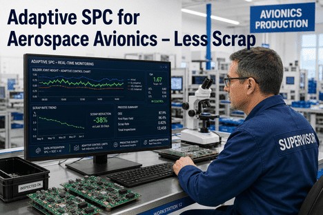
Our avionics line was running 12 product variants per week across three shifts. The SPC chart was generating 6 to 8 false alarms per shift on solder paste height alone. Operators had learned to ignore the chart entirely — every alarm was investigated, every investigation found nothing, and the corrective action log was full of entries that said the same thing: process was fine, limits were outdated. Within three weeks of deploying adaptive limits, the false alarm rate dropped to under 2 per shift. The alarms that remained were real. We caught a reflow temperature drift 35 boards before it would have produced a nonconforming solder joint — a defect that our static limits would have missed entirely because each individual measurement was within the old spec limits. Cpk on solder paste height moved from 1.42 to 1.74 and stayed there.

— Operations Director, Aerospace Avionics Assembly — IPC Class 3, 8 SMT Lines, 22 Product Variants

Conclusion

Cpk erosion in aerospace avionics is not a process stability problem — it is a limit architecture problem. Static UCL and LCL, calibrated during PPAP and reviewed at quarterly intervals, cannot track a process that changes with every material lot, product variant, solder profile, and shift transition. By the time the quarterly capability study detects that Cpk has fallen from 1.67 to 1.45, the defect population that caused the decline has already been produced, inspected, and either scrapped or reworked. Adaptive control limits replace this reactive cycle with a continuous self-tuning mechanism that recalculates UCL and LCL against the current process baseline every time a new measurement arrives. False alarms drop by 60 to 70 percent because the limits no longer fire on normal variation that the static limits mistakenly classified as out of control. Real signals are detected 3 to 5 times faster because the limits tighten when the process stabilises, providing earlier sensitivity to emerging drift. Cpk sustains above 1.67 across product variant transitions, material lot changes, and shift boundaries — because the limits reflect the process as it is running, not as it was running during a capability study conducted months ago.

The 2025 and 2026 evidence from aerospace electronics manufacturing is consistent and measurable. Plants deploying adaptive control limits report 60 to 70 percent fewer false alarms, 95 percent real alert proportion, Cpk sustained above 1.67 on critical characteristics across product families and material lot changes, and product variant changeovers that transition in milliseconds rather than 25 to 45 minutes. Every limit recalculation is logged automatically with statistical rationale, creating the AS9100-compliant documentation trail that demonstrates the quality programme actively maintains current, defensible control limits. The operations directors achieving these outcomes are the ones who deployed adaptive limits early, configured rolling window parameters per characteristic, and used the regime change classification engine to eliminate the transition-period false alarms that static systems cannot avoid.

iFactory's adaptive control limit platform is designed for operations directors in aerospace avionics who need control limits that track the real process — not the process that existed at the last qualification study. Book a Demo to see adaptive control limits configured for your avionics product portfolio and assembly line configuration, or talk to an expert about a free adaptive limit assessment for your aerospace avionics quality programme.

Frequently Asked Questions

The rolling window size is per-characteristic configurable based on the expected rate of process change and the measurement frequency. Characteristics with rapid drift potential — such as solder paste height where stencil wear progresses steadily — are typically set to a shorter window of 20 to 25 boards, providing faster response to emerging drift. Characteristics with stable behaviour — such as board thickness or laminate dimensions — use a longer window of 40 to 50 boards, providing greater statistical stability. The system's regime change detection automatically adjusts the effective window during transitions, expanding it when the process enters a known changeover state and contracting it when the process stabilises. The operations director configures window sizes during deployment based on historical drift rates per characteristic, and the values are adjustable in production if a parameter's behaviour changes. Talk to an expert about window size configuration for your specific avionics product portfolio.

The regime change classifier uses a combination of pattern recognition and process context signals. When a material lot change is logged in the system — either automatically through the ERP/MES integration or manually through operator entry — the classifier receives a context signal that a transition is in progress. During the configurable transition window, the system expects a shift in the process baseline and adjusts limits accordingly without triggering alarms. If no context signal is present and the ML model detects a statistically significant shift in the process distribution, the shift is classified as an assignable-cause event requiring investigation. The classifier also evaluates the shift's characteristics — rate of change, magnitude, covariance pattern across related parameters — to distinguish between gradual drift patterns that indicate tool wear and step-change patterns that indicate a material or setup change. The documented result is a false alarm rate during transitions that drops from 15 to 25 percent with static limits to under 5 percent with adaptive limits. Book a Demo to see the regime change classifier in operation on live avionics production data.

Yes. The platform maintains both adaptive limits and static specification limits simultaneously. The adaptive UCL and LCL drive the real-time control chart that operators use for daily process management. The static specification limits remain available for compliance reporting and PPAP comparison. Auditors reviewing the system see both sets of limits, the documentation trail for every adaptive recalculation, and the process context data that triggered each adjustment. The most common audit finding in AS9100 SPC programmes is not that the process was out of control — it is that the control limits in use have no documented rationale linking them to the current process state. Adaptive limits eliminate this finding by generating a complete documentation trail automatically: every limit change logged with the process data that triggered it, the statistical basis for the recalculation, and the classification that determined whether the change was common-cause or assignable-cause. This is a materially stronger compliance position than static limits that may have been calculated months or years ago with no recalculation record. Talk to an expert about configuring dual-limit display for your AS9100 audit requirements.

Adaptive control limits deploy as a software layer on top of existing inspection and measurement equipment — no hardware changes, sensor additions, or equipment replacement required. The platform connects to AOI systems, solder paste inspection stations, reflow oven temperature profilers, and in-circuit testers through standard industrial interfaces including REST APIs, database connectors, OPC-UA, and file-based data exchange. The adaptive limit engine processes the measurement data the existing equipment already produces and returns updated UCL and LCL values to the control chart display. Operators continue using the same workstations and dashboards they already know. The first line is typically integrated within 2 to 3 weeks, with additional lines deploying faster as connector templates are already configured. The platform runs shadow mode for the first week — generating adaptive limits alongside static limits without affecting production decisions — allowing the quality team to validate the regime change classification accuracy before activating adaptive limits as the primary control boundary. Book a Demo to see the integration architecture for your specific equipment set.

Static Limits Are Costing You Cpk Points Every Shift. Adaptive Limits Close the Gap. Get a Free Adaptive Limit Assessment for Your Avionics Line.
iFactory's adaptive control limit platform for aerospace avionics operations directors — self-adjusting UCL and LCL that recalibrate to every material lot, product variant, and solder profile transition, with ML-driven regime change detection, automated AS9100 limit change logs, and a 60-70% reduction in false alarms that restores operator trust and sustains Cpk 1.67+ across every shift.

Share This Story, Choose Your Platform!