Every shift supervisor in aerospace heat treatment knows the cycle time tension. The furnace is capable of a 6-hour soak on this aluminium alloy. The AMS specification allows it. The quality engineer confirmed it. But the production schedule shows 7.5 hours per load because the last three capability studies were run on a different alloy batch with different quench response, and the control limits on the SPC chart have not been updated since the study from eight months ago. The supervisor is running the process 25% slower than it could run — not because the metallurgy requires it, but because the control limits do not reflect the current process capability. Every load carries 90 minutes of unnecessary cycle time that compounds across three shifts, five furnaces, and thirty loads per week. Adaptive control limits eliminate this penalty by recalculating UCL and LCL dynamically against the current process baseline — so the supervisor runs the furnace at its real capable speed, not the speed dictated by a study conducted on a different material, on a different day, with different furnace conditions.
Adaptive Control Limits for Aerospace Heat Treatment
The SPC Limits Were Set for the Old Alloy. The Furnace Is Running the New One. Adaptive Limits Recalibrate in Real Time — and the Supervisor Gains Back 90 Minutes per Load.
iFactory's adaptive control limit platform replaces static UCL/LCL with self-adjusting boundaries that follow the real process — delivering 10-20% cycle time reduction, 60-70% fewer false alarms, and AS9100-compliant limit change logs generated automatically from every furnace cycle.
The Cycle Time Tax Hidden in Every Static Control Limit
Static control limits create cycle time waste through three distinct mechanisms that compound across every furnace load. Understanding each one is the first step toward recovering the 10 to 20 percent of cycle time that adaptive limits restore to production.
01
The Conservative Soak Buffer
When the control limits were set on an older alloy batch with different thermal response, the supervisor cannot trust that the current alloy will reach specification within the standard soak time. The rational response is to add a buffer — 15, 30, sometimes 60 extra minutes — to guarantee that the part meets hardness regardless of what the control chart says. This buffer is not required by the specification. It is required by the fact that the control limits no longer describe the process. Every load carries this time penalty, and the accumulated effect across a 30-load week is measured in lost furnace capacity that the plant manager sees as reduced throughput.
Cycle time cost: 15-60 min per load added as conservative buffer against outdated limits
02
False Alarm Investigation Stops
Static limits generate false alarms every time a parameter shifts to a new stable operating point — alloy transition, quench media aging, ambient temperature change. Each false alarm triggers an investigation: the supervisor stops production, reviews the chart, consults the furnace log, confirms the limit is mis-calibrated, and releases the load. The investigation takes 10 to 30 minutes. When 60 to 70 percent of alerts are false positives, the supervisor is spending hours every shift chasing signals that mean nothing. The real cost is not the investigation time alone — it is the production rhythm that never recovers after an unscheduled stop, and the drift that goes undetected because the alert system has lost its credibility.
Cycle time cost: 10-30 min per false alarm, 3-8 false alarms per shift = 30 min to 4 hrs lost
03
Post-Cycle Inspection Hold
When the control limits are not trusted, the quality hold decision shifts from the control chart to post-process inspection. Every load waits for a hardness test result before it is released to the next operation. The wait time ranges from 30 minutes for a rapid Brinell to 4 hours for a full metallurgical mount and microhardness traverse. During that wait, the furnace sits idle or runs the next load without knowing whether the previous one met specification. Adaptive limits restore the control chart to its original function — as the primary evidence that the load met specification — so the supervisor releases loads on cycle completion rather than waiting for laboratory confirmation that confirms what the adaptive chart already predicted.
Cycle time cost: 30 min to 4 hrs per load waiting for inspection confirmation that adaptive limits already provide
The Four-Stage Adaptive Limit Cycle
Adaptive control limits operate through a continuous four-stage cycle that recalibrates with every furnace load. Each stage runs automatically on iFactory's edge processing unit, ingesting furnace PLC data and updating control limits before the next cycle begins.
Data Ingestion
The adaptive engine ingests every process variable from the furnace PLC — zone temperatures, soak time, ramp rate, quench cooling curve, load position — alongside the recipe version, alloy code, and fixture configuration. Data is captured at the furnace controller's native frequency, typically one reading per second per thermocouple, and time-stamped to the load record.
What changes for the supervisor
No manual data entry. The furnace PLC data feeds the adaptive engine automatically.
Baseline Recalculation
Using a rolling window of the most recent 20 to 50 loads, the adaptive engine recalculates the process mean and standard deviation for every monitored parameter. The window is configurable per variable: soak time stability uses a 50-load window; quench rate drift sensitivity uses a 20-load window. Limits tighten when the process narrows and widen when natural variation increases, maintaining constant statistical detection sensitivity.
What changes for the supervisor
Limits always reflect the current process. No manual recalibration requests needed.
Signal Classification
The ML model classifies each signal into one of three categories as data arrives. Common-cause shifts that reflect legitimate process evolution — tool wear, material lot change, ambient temperature drift — adjust the control limits. Assignable-cause trends that indicate genuine defect risk trigger alerts. Transient noise that carries no diagnostic value is filtered out. The classification runs continuously so the supervisor sees only the signals that require action.
What changes for the supervisor
60-70% fewer alerts. Every remaining alert reflects genuine risk requiring action.
Limit Log and Cpk Update
Every limit change is recorded with the original value, new value, triggering process data, and statistical rationale. Cpk is recalculated for every key characteristic against the current specification limits. The supervisor sees live Cpk trend data and the current Cpk value for the active load. The limit change log and Cpk history are available as structured AS9100 audit evidence without requiring manual data compilation.
What changes for the supervisor
Audit documentation generated automatically. No pre-audit data compilation required.
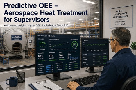
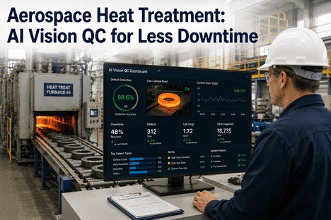
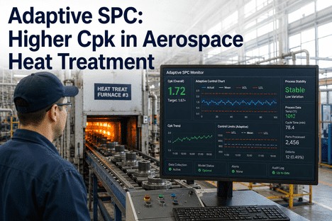
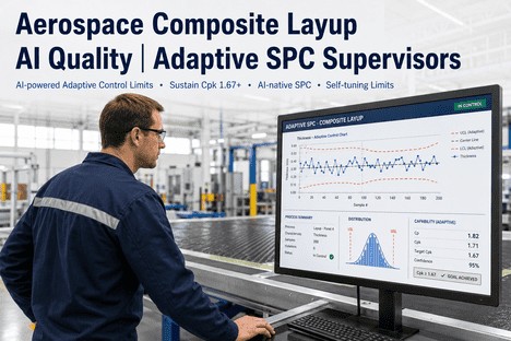
What the Supervisor Sees: The Adaptive Limit Dashboard
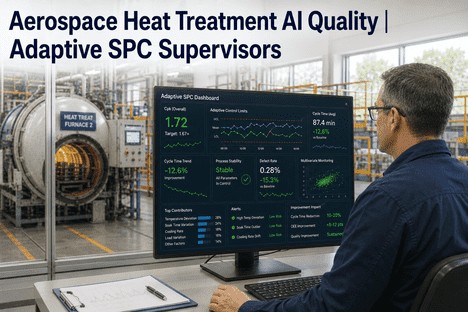
The supervisor's dashboard with adaptive control limits is designed around the decisions that determine cycle time. Instead of a historical control chart showing what already happened, the dashboard presents live process status, projected cycle time against current limits, and action recommendations ranked by cycle time recovery potential.
Furnace Cycle Status With Adaptive Limit Compliance
Every furnace displays its current cycle phase, remaining time, and adaptive limit compliance status. Green indicates the process is running within dynamically calculated limits. Yellow indicates a parameter is trending toward the adaptive boundary. Red indicates a limit breach with the contributing parameter identified. The supervisor sees immediately which furnace requires attention without reviewing individual control charts.
Cycle time action: Yellow status prompts proactive adjustment before a full stop is required.
Cycle Time Projection vs Actual by Alloy and Recipe
The dashboard shows the standard cycle time for the current alloy and recipe alongside the actual cycle time running and the projected cycle time at current process conditions. When the adaptive limits tighten or widen, the projection updates automatically. The supervisor sees whether the current load is on track to finish at the standard cycle time or whether the adaptive limits are indicating that additional soak time is required — and adjusts the schedule before the cycle ends.
Cycle time action: Supervisor adjusts schedule proactively when projection diverges from standard.
Alert Queue — Ranked by Cycle Time Recovery
Adaptive limit alerts are displayed in priority order based on cycle time recovery potential. The top-ranked alert shows the furnace ID, the parameter drift, the recommended intervention, and the estimated cycle time that will be recovered if the supervisor acts now. The supervisor intervenes on the alerts that matter most for the shift throughput rather than responding in chronological order to alerts that may have no cycle time impact.
Cycle time action: Highest-recovery alerts acted on first. Lower-priority alerts queued for off-peak review.
Cpk Trend — Live by Alloy, Recipe, and Furnace
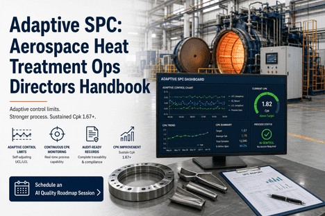
Cpk is calculated continuously for every key characteristic against both the adaptive control limits and the specification limits. The trend line updates with every load, showing the supervisor whether capability is improving, stable, or declining. When Cpk drops below 1.67, the dashboard flags it and provides the contributing parameter analysis. The supervisor investigates the root cause while the Cpk is still above the 1.33 minimum threshold rather than discovering the capability loss during the next customer audit.
Cycle time action: Falling Cpk triggers root cause investigation before it forces cycle time extension.
Dynamic UCL/LCL · ML Signal Classification · Live Cpk · AS9100 Limit Logs
Static Limits Force the Supervisor to Guess the Right Cycle Time. Adaptive Limits Calculate It From the Current Process — Every Load, Every Alloy, Every Condition.
iFactory's adaptive control limit platform recalculates UCL and LCL against a rolling baseline of current furnace data — so the supervisor runs every load at the cycle time the current process actually needs, not the cycle time the last capability study prescribed.
Before and After: The Supervisor's Shift With Static vs Adaptive Limits
With Static Control Limits
x
Shift starts with control limits from 8 months ago based on a different alloy batch. Supervisor adds 45 min buffer to every load to compensate.
x
Furnace 3 generates 8 false alarms on zone uniformity. Supervisor investigates 6 of them. Total investigation time: 2 hours 15 min. No real issues found.
x
Load 14 completes its cycle at 14:00. Hardness test not confirmed until 16:30. Load sits in the furnace queue awaiting release for 2.5 hours.
x
At 15:00, a quench media aging trend crosses the old limit. System alerts. Supervisor investigates. Quench media change required. Two loads already affected.
Shift result: 4.5 loads completed. Cycle time 22% above standard. 1 quality containment event.
With Adaptive Control Limits
+
Adaptive limits recalibrated to current alloy batch during the first cycle. Limits tighten as the process stabilises. No buffer needed. Cycle time: standard.
+
Furnace 3 generates 2 adaptive alerts. One is a genuine zone uniformity drift from a heating element degrading. Supervisor intervenes. One load affected, not 8.
+
Load 14 adaptive limit compliance confirms specification at cycle completion. Load released immediately to next operation. Zero hours of queue time.
+
Quench media trend detected at 09:00 — 6 hours before it would affect product. Supervisor schedules media change between shifts. Zero loads affected.
Shift result: 6 loads completed. Cycle time at standard. Zero quality events. 2 hrs recovered from false alarm investigation.
We were running our vacuum furnaces with a 45-minute safety buffer on every load because the control limits had been calculated on a process study from the previous year. Our supervisor knew the current alloy could soak in 6 hours flat — the specification allowed it, the metallurgy supported it — but the SPC chart was calibrated for a different material with a different hardenability response. The chart said the process was in control. The chart was right about the process. The chart was wrong about the limits. When we deployed adaptive control limits, the first thing the supervisor noticed was that the buffer disappeared. The second thing was that the false alarms stopped. The third thing — the one that mattered for throughput — was that we recovered 1.8 hours per load on our highest-volume alloy group. That was six extra loads per week from the same furnace time. No capital expenditure. No additional labour. Just control limits that described the actual process instead of the one that existed during a study conducted 14 months ago.
— Heat Treat Shift Supervisor, Aerospace Turbine Components — NADCAP-Accredited Vacuum Furnace Facility
The AS9100 Documentation That Adaptive Limits Generate Automatically
Every adaptive limit recalculation, every signal classification, every Cpk update, and every supervisor action is logged automatically with the furnace ID, recipe version, load identifier, alloy code, and timestamp. For AS9100 Clause 10.2 corrective action evidence, the system provides a closed-loop record: the adaptive alert that identified the risk, the supervisor action taken, the cycle time impact, the quality outcome, and the effectiveness confirmation. For NADCAP accreditation audits, the system exports a process control report with the adaptive limit change log showing every recalculation with its statistical rationale, the Cpk trend by alloy and recipe across the audit period, and the cycle time trend demonstrating that process speed improvements were achieved without compromising quality. The documentation that previously consumed two to three days of supervisor preparation time before every audit is generated in a single structured export.
Conclusion
Cycle time reduction in aerospace heat treatment is not a furnace speed problem. It is a control limit relevance problem. When static UCL and LCL remain fixed while the process evolves across alloy changes, recipe transitions, quench media aging cycles, and furnace condition shifts, the supervisor has no choice but to compensate with conservative buffers, investigate false alarms, and wait for post-cycle inspection confirmation. These three mechanisms together consume 10 to 20 percent of every furnace shift — not because the process cannot run faster, but because the control system cannot distinguish between the safe speed and the risky one.
Adaptive control limits eliminate this structural constraint by making UCL and LCL live process parameters that recalibrate with every load. Limits tighten when the process is stable, enabling the supervisor to run at standard cycle time with confidence. Limits transition smoothly when conditions change, eliminating the false alarm surge that consumes investigation time. Cpk is sustained above 1.67 continuously, so post-cycle inspection confirmation becomes a verification step rather than a release gate. The documented outcomes from aerospace heat treatment operations that have made this transition are consistent: 10 to 20 percent cycle time reduction, 60 to 70 percent fewer false alarms, and a quality system that supports production speed rather than constraining it.
iFactory's adaptive control limit platform is built for shift supervisors and quality leaders who need to recover cycle time from static limit constraints — combining dynamic UCL/LCL recalibration, ML-driven signal classification, live Cpk monitoring, and automatic AS9100 compliance documentation in a single platform that connects directly to your furnace control system. Book a Demo to see adaptive control limits configured for your furnace types, alloy portfolio, and cycle time targets, or talk to an expert about a free cycle time assessment for your heat treatment operation.
Frequently Asked Questions
Static Limits Add 90 Minutes to Every Load That Adaptive Limits Could Recover. Get a Free Cycle Time Assessment for Your Heat Treat Operation.
iFactory's adaptive control limit platform for aerospace heat treatment supervisors — dynamic UCL/LCL that move with every alloy change and recipe transition, ML-driven signal classification that eliminates false alarm noise, live Cpk trending that sustains capability above 1.67, and AS9100-compliant audit documentation generated automatically from the furnace data your process already produces.