Every shift supervisor in aerospace engine assembly knows the feeling. The SPC chart on the CMM workstation shows a point outside the control limits. The operator flags it. The supervisor reviews the part. The measurement looks valid. The corrective action log requires an entry. But deep down, the supervisor knows the limits on that chart were set during qualification on a different material batch, with a different tooling setup, and a different environmental baseline. The point outside the limit is not necessarily a defect — it is a signal from a control system calibrated for a process that no longer exists. The real question is whether this signal is a false alarm or a genuine precursor to a nonconformance. Adaptive control limits remove that ambiguity by making the limits reflect the current process state, not the state that was qualified 14 months ago.
Dynamic UCL/LCL · Western Electric Rule Engine · False Alarm Elimination · AS9100 Limit Change Logs
When Control Limits Are Static, Every Out-of-Control Signal Becomes a Supervisor's Dilemma — Is It Real or Is It Stale Data? Adaptive Limits Remove the Question.
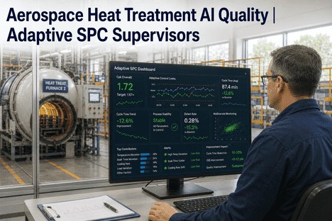
iFactory's adaptive SPC platform gives engine assembly supervisors dynamic control limits that move with the process, Western Electric rule evaluation on every part, and AS9100/NADCAP-compliant limit change logs generated automatically from every monitored characteristic.
The Static Limit Problem: Why Fixed Control Limits Cannot Keep Up With Engine Assembly
Aerospace engine assembly is a multi-state process that transitions through materially different operating regimes over any production week. The warm-up shift at the start of a new programme run, the steady-state mid-run operation, the thermal drift during a long assembly cycle, the material batch change between turbine module sets, the tooling swap after a critical fastener driver reaches its life limit — each regime has a different natural variation baseline, and a control limit that is appropriate for one regime is inappropriate for all the others. Yet standard SPC practice calculates limits once during a Phase I capability study and freezes them indefinitely. The result is a control system that fires false alarms during regime transitions and misses genuine drift during steady-state operation — the worst of both worlds.
The False Alarm Cycle
Static limits are too narrow for the warm-up regime and too wide for the steady-state regime. The operator sees 5 to 8 out-of-control signals per shift during transitions. 80% are false alarms driven by limits that do not match the current process state. The operator stops responding. The supervisor investigates and finds no defect. The corrective action log accumulates entries for events that were never real. Audit scrutiny reveals a chart full of uncorrected signals and a corrective action log that documents noise rather than genuine process events — a finding that undermines the credibility of the entire quality programme.
The Adaptive Limit Solution
Adaptive limits continuously recalculate UCL and LCL against a rolling window of the most recent production data — typically 25 to 50 parts. When the process transitions to a new regime (warm-up, material change, tooling swap), the limits adjust to the new baseline within a configurable transition window. False alarms during transitions are eliminated. When the process stabilises, the limits tighten automatically, providing earlier detection of real drift. The operator sees 1 to 2 alerts per shift. 95% of alerts are genuine assignable-cause events requiring action. The corrective action log reflects real process interventions, not noise.
Static Limits
5-8
False alarms per shift
Adaptive Limits
1-2
True alerts per shift
Operator Trust
95%
Alert response rate restored
Shift Detection
3-5x
Faster drift detection
Audit Findings
0
Limit-related NCs with adaptive logs
How Adaptive Control Limits Work in Engine Assembly
Adaptive control limits operate through a continuous four-stage cycle that runs independently for every monitored characteristic across the assembly line. The supervisor does not configure or adjust this cycle — it runs automatically, and the supervisor interacts with the output through the dashboard and alert system. Understanding the cycle is essential because it changes what the supervisor needs to verify, document, and respond to on each shift.
1
Rolling Data Window
Every new measurement enters a rolling window of the most recent 25 to 50 parts for that characteristic. The window length is configured per characteristic based on production rate and process dynamics — tighter for high-volume bore measurements, wider for low-volume CMM checks. Outdated data exits the window automatically.
2
Limit Recalculation
UCL and LCL are recalculated from the rolling window using EWMA-based estimation that gives greater weight to recent points. Confirmed out-of-control points from assignable-cause events are excluded to prevent real excursions from widening the limits.
3
Pattern Classification
Each new point is evaluated against all eight Western Electric rules simultaneously. The engine classifies the event as common-cause (limits adjust) or assignable-cause (alert fires). Transient noise is ignored. Sustained trends trigger supervisor-level notification with the specific rule violated and the drift direction.
4
Audit Logging
Every limit recalculation is logged automatically — the timestamp, the triggering classification, the previous and new limit values, the window size, and the algorithm parameters. The log is searchable by characteristic, date range, and part number, and is exportable for AS9100 and NADCAP audit review without manual compilation.
The Western Electric Rule Engine — What the Supervisor Sees and Why It Matters
iFactory's adaptive SPC engine evaluates all eight Western Electric rules on every new data point across every monitored characteristic. Most legacy SPC tools evaluate only the first four rules (single-point, two-of-three, four-of-five, and eight-consecutive) and omit the pattern-based rules (six-consecutive trending, fifteen-consecutive stratification, fourteen-consecutive alternating, and eight-consecutive mixture). In engine assembly, where systematic patterns from tool wear, thermal cycling, and fixture creep are common, the missing rules are often the ones that detect the earliest signs of drift. The supervisor receives a consolidated alert for each rule violation — the specific rule number, the characteristic, the current value and limit status, and the number of consecutive points contributing to the pattern. This eliminates the need for manual chart reading and pattern interpretation.
Stratification — less variation than expected. Data from mixed process streams.
Data from multiple assembly stations or fixtures plotted as a single stream, masking individual variation
R7: 14 consecutive alternating
Systematic oscillation between two levels. Two alternating process states.
Two operators alternating on same station with different techniques, dual-fixture system with misalignment
R8: 8 consecutive beyond 1-sigma (none in C zone)
Mixture — data from two distinct distributions. Indicates bimodal process.
Two material suppliers delivering different property distributions, measurement system bias between two CMM fixtures
S
Supervisor Alert — What You See on the Dashboard
When a Western Electric rule fires, the supervisor dashboard displays the characteristic name, the rule number, the current measurement value relative to the adaptive limits, and the number of consecutive points in the pattern. For Rule 5 (trending), the dashboard also shows the slope estimate and the projected time to limit breach at the current drift rate. The supervisor evaluates the alert, assigns an investigation if needed, and logs the disposition — all from the dashboard without navigating to a separate module.
A
Audit Trail — What the Record Shows
Every Western Electric rule violation is logged with the rule number, the characteristic, the measurement value, the adaptive limit values at that time, the part serial number, and the supervisor disposition. The log is searchable and exportable. An auditor reviewing the record sees that every assignable-cause event was evaluated, every false alarm (from the pre-adaptive period) has a documented explanation, and every genuine event has a corresponding corrective action.
How the Supervisor Uses Adaptive Limits to Manage Each Shift
Adaptive control limits change the supervisor's shift workflow. Instead of spending the first hour of every shift reviewing control charts to distinguish real signals from stale-limit noise, the supervisor reviews a filtered alert queue that contains only genuine assignable-cause events. The workflow shifts from signal interpretation to response execution.
1
Shift Start Review
Supervisor opens the adaptive SPC dashboard and reviews:
Active alerts from the previous shift — rule violations that need disposition
Current adaptive limit status for each active characteristic — limits that tightened or widened overnight
Cpk trend for the previous shift's production run — any characteristic approaching the warning threshold
2
Alert Response
When a Western Electric rule fires during the shift:
The alert shows the rule number, characteristic, and measurement value
Supervisor assigns the alert to the responsible operator for investigation
Operator performs the root-cause check and logs the finding
Supervisor reviews and closes the alert with a disposition — or escalates to engineering
3
Process Transition Management
When a material batch change, tooling swap, or programme transition occurs:
Supervisor logs the transition event in the system
The adaptive limit engine registers the event and initiates a transition window
Limits adjust to the new process baseline over the configured window length
No false alarms are generated during the transition — limits move with the shift
4
Audit Documentation Review
Before an audit, the supervisor reviews:
Limit change log — every adaptive limit adjustment with documented rationale
Alert disposition log — every assignable-cause event with supervisor action recorded
Cpk trend report by part number — live capability history for the audit period
Corrective action log — linked to specific alerts with effectiveness evidence
When I started on this line, I spent the first 90 minutes of every shift reviewing control charts, trying to figure out which out-of-control signals were real and which were just the limits being wrong. The operators had learned to ignore most of them because 80% turned out to be nothing. With adaptive limits, my alert queue is clean at shift start. When an alert does fire, I know it is real because the limits are calibrated to what the process is actually doing right now. The operators trust the alerts again. The corrective action log shows real events, not noise. Our last NADCAP auditor reviewed the limit change log and said it was the most transparent control limit documentation he had seen in an engine assembly facility.
The Audit Documentation That Adaptive Limits Generate Automatically
The most common audit finding in aerospace engine assembly SPC programmes is not that the process was out of control. It is that the control limits in use have no documented rationale linking them to the current process state. A limit set during a capability study conducted 14 months ago, with no recalculation record and no documented review, is an audit finding because the organisation cannot demonstrate that the limits are still valid. Adaptive limits eliminate this finding by generating a complete documentation trail automatically — every limit change logged with the process data that triggered it, the statistical basis for the recalculation, and the classification that determined whether the change was common-cause or assignable-cause.
Documentation 01
Limit Change Log
Every limit recalculation is recorded with timestamp, characteristic, previous UCL and LCL, new UCL and LCL, rolling window size, triggering event classification, and algorithm parameters. Searchable by part number and date range. Exportable as a structured document for audit submission.
Documentation 02
Alert Disposition Record
Every Western Electric rule violation is logged with the rule number, characteristic, measurement value, adaptive limits at event time, part serial number, operator investigation result, supervisor disposition, and any corrective action opened. Forms the complete SPC response record for audit.
Documentation 03
Cpk Trend Report
Live Cpk per characteristic calculated from the adaptive limit window. Historical Cpk by part number for any date range. Both adaptive Cpk (against dynamic limits) and static Cpk (against original specification limits) are available — giving auditors both current and baseline capability views.
Conclusion
The fundamental problem that adaptive control limits solve is not statistical. It is operational. Static limits create a control system that operators cannot trust and supervisors cannot defend. Every shift produces a stream of out-of-control signals that are mostly false alarms generated by limits that do not reflect the current process state. Operators learn to ignore the chart. Supervisors spend their time investigating noise. The corrective action log fills with entries that document nothing of substance. And when the AS9100 or NADCAP auditor arrives, the control chart tells a story of an untrusted system with no documented rationale for its limits — a finding that the corrective action log confirms rather than refutes.
Adaptive control limits restore the operational integrity of the SPC system. Limits that move with the process generate alerts only when real assignable-cause variation is present. Operators trust the alerts and respond. Supervisors investigate events that matter. The corrective action log documents genuine process interventions. And the audit trail — the limit change log, the alert disposition record, the Cpk trend history — is generated automatically from the same system that the supervisors and operators use every shift, not assembled manually from paper records and machine logs after the fact.
iFactory's adaptive SPC platform is purpose-built for aerospace engine assembly supervisors who need a control system their team trusts and their auditors accept. Book a Demo to see adaptive control limits configured for your engine assembly characteristics and part numbers, or talk to an expert about a free audit-readiness assessment for your current SPC programme.
Frequently Asked Questions
AS9100 Rev D Clause 8.5.1 requires documented in-process verification, and Clause 8.1 requires that statistical techniques be applied appropriately with documented rationale. Adaptive control limits satisfy these requirements through the automatic limit change log that records every recalculation event — the timestamp, the characteristic, the previous and new limit values, the rolling data window size, the classification (common-cause or assignable-cause), and the algorithm parameters used. The log is searchable and exportable in a structured format suitable for direct inclusion in audit documentation. An auditor reviewing the adaptive limit history sees a controlled process where every limit change has a documented rationale connected to current production data — a materially stronger position than a single Phase I capability study that has not been reviewed or recalculated in 14 months. The key distinction is that adaptive limits do not change randomly or without traceability. Each change is logged with the statistical justification that produced it, and the log is available on demand. Talk to an expert about configuring the adaptive limit change log format for your AS9100 documentation system.
No — if the adaptive limit engine is implemented correctly. The key design feature that prevents this is the distinction between common-cause and assignable-cause classification. When a new data point or sequence of points is classified as assignable-cause variation based on Western Electric rule evaluation, those points are excluded from the limit recalculation window. This ensures that real excursions do not pull the limits outward and mask future drift. Common-cause variation — the natural random variation that defines the process at its current state — is included in the window, so limits adjust appropriately when the process establishes a new stable baseline following a known transition (material batch change, tooling swap, programme transition). The supervisor also has the ability to set a maximum allowable limit width per characteristic, which caps how wide the adaptive limits can extend regardless of the data window. This provides a hard boundary against any scenario where the adaptive engine might be too permissive. Book a Demo to see the assignable-cause exclusion logic and maximum limit width configuration for your characteristics.
Initial configuration for an engine assembly line typically requires 30 to 60 days from data collection to live adaptive operation. The platform needs three data inputs per critical characteristic: the specification limits (USL and LSL), the current static control limits if applicable, and a minimum of 100 production readings per characteristic to establish the baseline EWMA parameters. If historical SPC data is available for the past 6 to 12 months, the initial calibration can be accelerated significantly. During the configuration period, the adaptive engine runs in shadow mode — generating dynamic limits in parallel with the existing static limits without influencing operator or supervisor decisions. This allows the quality team to validate the adaptive limit behaviour against the known process history and confirm that the false alarm reduction and detection sensitivity meet expectations before transitioning to live operation. Book a Demo to see a sample configuration timeline for an engine assembly line with your characteristic profile.
Yes. The adaptive limit engine is data-type agnostic — it operates on any characteristic that generates continuous measurement data, including torque values from fastener drivers, clearance measurements from feeler gauge or laser systems, alignment readings from optical trackers, runout measurements from dial indicators, pressure test results from seal integrity checks, and flow test data from fuel system verification. Each characteristic type has its own configurable rolling window size, EWMA parameters, and Western Electric rule sensitivity settings. Torque data, which typically has tight natural variation and fast tool-wear drift, benefits from a shorter window (20 to 30 data points) and tighter EWMA weighting. Clearance and alignment data, which have wider natural variation driven by thermal and assembly stack-up effects, typically use a longer window (40 to 60 data points) with more conservative EWMA weighting. The supervisor configures these parameters per characteristic during initial setup, and the adaptive engine manages them from that point forward. Talk to an expert about configuring adaptive limits for your specific characteristic types across engine assembly stations.
A Control Limit That Has Not Changed in 14 Months Is Not a Safety Net — It Is a Liability. Adaptive Limits Keep Your SPC System Current, Trusted, and Audit-Ready on Every Shift.
iFactory's adaptive SPC platform for aerospace engine assembly supervisors — dynamic control limits with full Western Electric rule evaluation, automatic limit change logging for AS9100 audit compliance, and a 60-70% reduction in false alarms that restores operator trust in the control system.