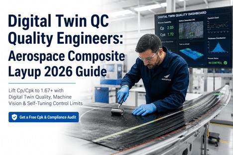
The AFP cell at Ply 22 is running clean. First-pass yield this shift: 91%. Acceptable on paper — but the two panels scrapped last fortnight tell a different story. Both failed post-cure NDT. Both were traced to fibre orientation drift that began at Ply 8. No alert fired. No correction was made. The control chart showed the process in control. The chart was wrong — because the limits it was using had been frozen at qualification six months ago, before that batch of prepreg arrived, before the compaction roller started to show wear, before the summer temperature shift changed the tack profile. Digital twin quality for aerospace composite layup replaces that frozen chart with a live process model that updates with every tow pass. This guide shows AFP operators and line technicians how digital twin QC works on the cell floor, what it means for AS9100 and NADCAP audit readiness, and why the operators who use it consistently hold first-pass yield above 96%.
Digital Twin QC · AFPM Composite Layup · AS9100/NADCAP
Your Control Limits Were Set Last Quarter. The Process Changed Last Shift.
Digital twin quality delivers self-tuning SPC, live Cpk per ply, and pre-breach operator alerts so every cure decision rests on current-state data — not a qualification snapshot from six months ago.
What Is Digital Twin Quality for Aerospace Composite Layup?
Digital twin quality in composite layup is not a simulation or a digital model of the part. It is a live, data-driven process control layer that sits between the AFP machine controller and the operator display, ingesting every tow-pass measurement — gap width, fibre orientation, overlap dimension, surface height deviation — and comparing it against a process model that updates continuously rather than once per qualification cycle. The digital twin is the statistical identity of the process as it is running right now, not as it was running during the PPAP run six months ago.
For AFP cell operators, the difference is tangible. Static SPC tells you a characteristic has breached the UCL after the fact. Digital twin QC tells you the characteristic is trending toward the UCL while you still have 8 to 12 tow passes to adjust AFP parameters and pull it back. That shift — from reactive limit detection to predictive drift correction — is what moves first-pass yield from 91% to 97% and keeps it there through material batch changes, head wear cycles, and seasonal environmental variation.
96%+
Sustained first-pass yield reported by AFP operations running digital twin QC with self-tuning control limits for more than six months across multiple part programmes
70%
Reduction in post-cure scrap within the first two production cycles after deploying real-time defect detection integrated with AFP parameter feedback
12:1
ROI ratio documented across aerospace composite programmes where digital twin QC eliminated cure-committed scrap from detectable process drift
How Digital Twin QC Works on the AFP Cell Floor
Digital twin quality for aerospace composite layup is a three-layer architecture that transforms raw sensor data into operator action. Each layer solves a specific problem that static SPC cannot address. Together they create a closed-loop quality control system that operators interact with through a single dashboard.
LAYER 1
Continuous Ply-Level Data Ingestion
Machine vision arrays mounted on the AFP head measure every tow pass at sub-millimetre resolution. Gap width, fibre orientation angle, overlap dimension, and tow-edge surface height are recorded and tagged with ply coordinate, material batch ID, AFP head operating hours, and ambient temperature and humidity at the point of deposition. This metadata layer is critical: it allows the digital twin to distinguish between a real gap trend and the expected tack shift that occurs when the layup room temperature drops 3 degrees Celsius at shift change. Without this context, every deviation looks like a process problem. With it, the model filters environmental noise and surfaces only genuine process drift.
Sub-mm per-pass resolution
Environmental metadata tagging
Batch and head-hours context
LAYER 2
AI-Native SPC With Self-Tuning Control Limits
The multivariate ML model ingests the measurement stream and recalculates the UCL and LCL from live data — not from frozen qualification baselines. Limits narrow when the process is stable, giving operators tighter tolerance bands that catch drift earlier. Limits widen appropriately for steering-zone geometry where higher deviation is structurally acceptable. When a new material batch arrives or the AFP head reaches a maintenance interval, the model detects the distribution shift within three to five ply passes and adjusts the control model before a systematic defect pattern accumulates. Cpk updates with every ply measurement. Cross-panel trend detection identifies whether a gap distribution drifting right across six consecutive panels is an AFP head parameter issue or a material batch characteristic — reducing root cause investigation from days to under an hour.
Per-ply Cpk update
Geometry-zone-aware limits
Cross-panel drift trending
Batch-change adaptation
LAYER 3
Operator Alert and Corrective Action Interface
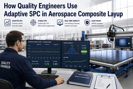
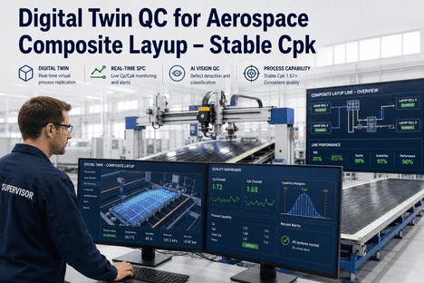
The operator dashboard displays live Cpk for each quality characteristic, colour-coded capability status, the current control chart with self-tuning limits rendered in real time, and a shift-level OEE Quality score. Alerts fire before the limit is breached — when the trend direction and velocity indicate the characteristic will cross the control boundary within a defined number of passes. Each alert includes the specific characteristic drifting, its current value, the limit it is approaching, and a suggested AFP parameter correction drawn from the historical correction database. The operator can accept the suggestion, log an alternative correction, or override. Every action is recorded with timestamp and operator ID, building the AS9100 audit trail as a by-product of normal production.
Pre-breach drift alert
Live OEE Quality score
Suggested AFP correction
Auto-logged AS9100 record
We were running static SPC with limits set during the original PPAP. The steering zones on our fuselage panels were generating alerts every third panel. Operators had learned to ignore the amber flags — they treated every steering-zone signal as expected variation. When a genuine fibre orientation drift appeared on a flat section, it went unnoticed until post-cure NDT flagged the panel. Root cause: a compaction roller wear condition that had been developing for two weeks. The pass-level data had been showing the trend since day three. No one saw it because the limits were too wide on the flat zones and too narrow on the steering zones. Digital twin QC would have flagged the drift at pass four on day one.
— Quality Systems Engineer, Primary Aerostructures Programme
The Operator Dashboard: What the AFP Cell Technician Sees
The digital twin quality interface is designed for operators who need to make decisions at layup speed, not for quality engineers analysing historical data. Every element of the display serves one purpose: tell the operator what is happening to the process right now, and what to do about it if something is wrong.
Live Capability Status
Colour-coded per-characteristic display — green for Cpk above 1.33, amber for trending between 1.0 and 1.33, red for below 1.0. Operators see immediately which characteristics need attention without interpreting control charts.
Trend Velocity Indicator
Arrow indicators show not just whether a characteristic is drifting, but how fast. A slow drift over 15 passes is handled differently from a sharp shift over 3 passes. The interface distinguishes them so operators prioritise correctly.
Correction Suggestion Engine
When an alert fires, the system displays a specific AFP parameter adjustment drawn from the historical database of successful corrections — compaction force, deposition speed, or heating zone temperature. Operators accept, modify, or override with a single tap.
Shift-Level OEE Quality Score
The Quality factor of OEE updates with every ply completion, not at shift end. Operators see their first-pass yield contribution in real time and can correlate it directly with their correction actions.
AS9100 and NADCAP Compliance: How Digital Twin QC Builds the Audit Record Automatically
For AS9100-registered aerospace operations and NADCAP-accredited composite layup facilities, the audit trail is not optional. Clause 8.5.1 requires documented evidence of process control under defined operating conditions. Clause 8.6 requires a documented basis for product release. Clause 10.2 requires root cause and corrective action documentation for every nonconformance. Meeting these requirements manually consumes engineering hours and still produces records that auditors challenge. Digital twin quality for aerospace composite layup generates all three classes of evidence automatically, at the point of production, linked to specific ply passes and operator actions.
AS9100 Clause 8.5.1
Process control evidence generated per ply from live digital twin data — control limit history, measurement records, and environmental conditions logged automatically without operator data entry
AS9100 Clause 8.6
Product release basis at cure authorisation — current-state Cpk per characteristic with full measurement traceability, not a static chart from the qualification run filed six months ago
AS9100 Clause 10.2
Root cause and corrective action linked to specific process parameters and operator actions — cross-panel pattern detection reduces investigation from days to under one hour
Audit Requirement
Without Digital Twin QC
With Digital Twin QC
Process control evidence compilation
3-5 days pre-audit
Export button
Cpk basis for product release
Qualification-era estimate
Live per-characteristic Cpk
Defect root cause investigation
2-5 days manual
Under 1 hour
NADCAP parameter logging
Manual log sheets
Auto-logged per pass
From Sensor Data to Cure Decision: The Digital Twin Quality Pipeline
Understanding how raw sensor data becomes a cure authorisation decision helps operators see why digital twin QC catches what static SPC misses. The pipeline has four stages, and the speed at which data moves through each stage determines whether an operator can intervene or can only report loss.
Sub-mm measurement per tow pass
AI vision arrays measure gap, orientation, overlap, and surface deviation at every pass with environmental context. Data volume: 10,000+ data points per ply.
ML-driven SPC with self-tuning limits
Multivariate model compares each measurement against live process distribution, recalculates UCL/LCL, updates Cpk, and evaluates Western Electric rules. Latency: sub-second per pass.
Pre-breach trend notification
System fires alert when trend velocity and trajectory indicate the characteristic will breach the control limit within a configurable number of passes. Includes suggested AFP parameter correction.
Operator correction and cure authorisation
Operator accepts or modifies suggested AFP parameter change. System logs action with timestamp. At cure authorisation, dashboard presents current-state Cpk for every characteristic as the release basis.
Four Things Self-Tuning Limits Do That Static UCL/LCL Cannot
The predictive capability of digital twin quality for aerospace composite layup is not a feature of the ML model alone. It is a direct consequence of control limits that update from live data. Static limits are set once and held until the next process review, which in many aerospace programmes is every 6 to 12 months. Self-tuning limits respond to the process as it actually runs. Here is what that means for the AFP cell operator.
Material Batch Transitions Stop Being Yield Events
A new prepreg batch arriving mid-production shifts tack and drapability. Static limits treat this as noise until the cumulative drift breaches the threshold. Self-tuning limits detect the step-change within 3-5 ply passes and update the control model before the first gap trend accumulates into yield loss.
AFP Head Wear Becomes a Trend Instead of a Surprise
Compaction roller wear increases gap width at tow edges gradually. Static limits catch this only at breach. Self-tuning limits tighten around the live distribution, surfacing the drift and triggering a maintenance alert before any panel is produced out of tolerance.
Seasonal Temperature Variation Stops Generating False Alarms
Prepreg tack varies with layup room temperature and humidity. A programme qualified in January produces different gap distributions in July. Self-tuning limits condition on environmental inputs, removing false alarms from expected seasonal variation while keeping operator focus on genuine process deviation.
Steering Zones and Flat Regions Get Appropriate Limits
A global UCL applied across the whole ply surface generates constant false alarms in steering zones and misses real deviation in flat zones. Self-tuning limits apply geometry-aware control models calibrated to ply coordinate geometry, not averaged across the entire part.
Live Cpk · Self-Tuning Limits · Pre-Breach Alerts
The Process You Are Running Right Now Is Not the One You Qualified Last Year. Your Control Limits Should Know That.
iFactory digital twin QC updates every control limit and Cpk with every ply measurement — so every cure authorisation is based on current-state process data, not frozen qualification baselines. See it running on your AFP cell data.
Conclusion
First-pass yield in aerospace composite layup is not a post-cure metric. It is a real-time process state that operators can influence on every shift, at every ply, when the quality system delivers the right signal at the right time. Digital twin quality for aerospace composite layup connects the operator directly to the process intelligence that moves yield: AI-native SPC that captures deviation at sub-mm resolution, self-tuning control limits that remain statistically valid as process conditions evolve from batch to batch and season to season, and an operator interface that converts complex process data into a correction action in seconds.
The AFP operations that consistently sustain first-pass yield above 96% share a common characteristic: their operators see the process trending before it drifts out of tolerance, and they have clear, data-backed guidance on what to adjust. Digital twin QC delivers exactly that — and builds the AS9100 and NADCAP complaint documentation record as a by-product of normal production, not as an additional administrative burden.
iFactory's digital twin quality platform is purpose-built for AFP composite layup operations — integrating with existing AFP controllers and MES systems to deliver live adaptive Cpk, self-tuning SPC limits, and automated AS9100 build records without changing the operator workflow. Book a Demo to see digital twin QC running on a composite layup use case matched to your part geometry and process profile, or Talk to an Expert to discuss first-pass yield targets for your specific programme.
Frequently Asked Questions
Every Ply Is a Quality Decision. Make It With Live Data, Not Last Quarter's Baseline.
iFactory digital twin quality for aerospace composite layup — live Cpk, self-tuning SPC limits, pre-breach operator alerts, and automated AS9100/NADCAP build records. Purpose-built for AFP cell operators.