Electrical failures rarely announce themselves with a single dramatic event. A loose connection runs slightly warm for months, an insulation system degrades a few percentage points a year, a breaker's trip mechanism goes untested through several maintenance cycles, and then one ordinary Tuesday a kiln drive MCC trips the entire process to a stop that nobody saw coming. In a cement plant where a single unplanned electrical outage can cost more in lost production than a year of testing would have, the case for disciplined switchgear, MCC, and cable maintenance is almost entirely about catching degradation while it is still a data point rather than an incident. Book a Demo to see how continuous thermal and load trending turns that degradation into a visible trend instead of a surprise.
The Power Distribution Chain Is Only as Reliable as Its Weakest Test-and-Inspect Interval
From the utility incoming feed through main switchgear, step-down transformers, motor control centers, and out to the motor feeders themselves, every link in a cement plant's electrical chain has its own failure mode and its own appropriate test schedule. Treating the whole system with one generic PM plan leaves the highest-consequence links under-tested and the lowest-risk links over-tested.
Five Links, Five Different Failure Modes — Mapping the Chain From Utility Feed to Motor
A cement plant's electrical system is a chain, and like any chain it fails at its weakest link rather than uniformly across its length. Mapping the chain from incoming utility power down to the individual motor feeder makes clear that each stage carries a distinct risk profile, and that a maintenance program built around those differences catches far more failures than one built around a single blanket schedule.
Utility Incoming
Primary metering and protection relays. Failure here affects the entire plant, so relay coordination testing and incoming breaker maintenance carry the highest consequence of any stage in the chain.
Main Switchgear
Medium-voltage breakers distributing power to major process areas. Contact wear, insulation degradation, and trip mechanism reliability are the primary concerns, and this stage typically carries the plant's highest arc-flash energy exposure.
Step-Down Transformers
Convert medium voltage to utilization voltage for MCCs and large motors. Oil condition, winding insulation, and cooling system integrity are the main failure drivers, developing slowly enough that trending catches most problems well ahead of failure.
Motor Control Centers
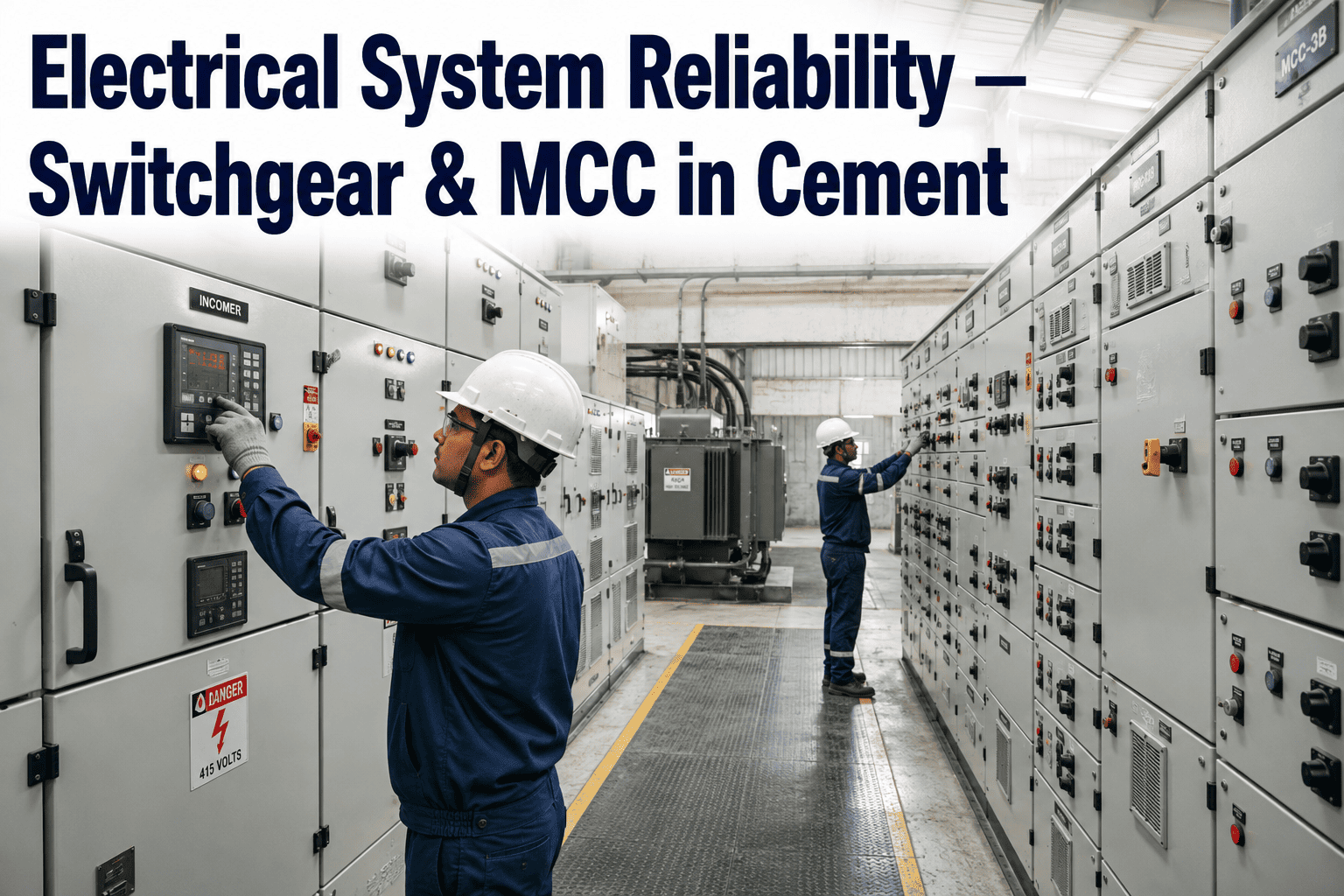
House the individual starters, contactors, and protection devices for kiln, mill, and fan motors. High switching frequency and vibration exposure make loose connections and contact wear the dominant failure mode here.
Cable and Feeder Circuits
Carry power from MCCs to individual motors and process equipment, often routed through harsh dust, heat, and vibration environments that accelerate insulation aging faster than cables in a cleaner electrical room.
The Four Tests That Catch Most Switchgear Degradation Before It Becomes a Trip
Switchgear maintenance built around a standard test set, performed at the right interval, catches the overwhelming majority of degradation modes before they progress to failure. Skipping any one of these four tests leaves a specific and predictable blind spot in the maintenance program.
Infrared Thermography
Identifies loose or high-resistance connections by detecting abnormal heating under load, typically performed quarterly on energized switchgear and MCCs as one of the few tests that can be done without an outage.
Insulation Resistance Testing
Measures the condition of insulation between conductors and ground, following IEEE 43 guidance, and trending the results over successive tests reveals moisture ingress or insulation aging long before it causes a fault.
Contact Resistance Testing
Measures resistance across breaker contacts and bus connections following NETA test guidelines, catching contact wear and connection degradation that infrared alone may miss at lower load conditions.
Breaker Functional Trip Testing
Verifies that protection relays and trip mechanisms actually operate correctly under simulated fault conditions, the only test on this list that confirms the breaker will do its job during a real fault rather than just that it looks healthy.
Which Link in Your Chain Hasn't Been Tested on Schedule?
iFactory tracks thermal trends and load history across switchgear, MCCs, and transformers continuously, flagging assets that are drifting toward failure between scheduled test intervals.
Oil Analysis, Power Factor, and Cable Insulation — What Each Test Actually Tells You
Transformers and cables both fail slowly by nature, which is exactly why trending, rather than a single pass or fail reading, is the right way to interpret their test results. A single dissolved gas analysis reading in isolation says relatively little; the same reading compared against six months of prior results says a great deal about whether a transformer's internal condition is stable or actively deteriorating.
| Test | What It Reveals | Typical Frequency |
|---|---|---|
| Dissolved Gas Analysis (Oil-Filled) | Internal arcing, overheating, or insulation breakdown byproducts | Annual, semi-annual for critical units |
| Insulation Power Factor | Overall insulation system condition and moisture content | Every 1-3 years |
| Cable Insulation Resistance / VLF | Insulation degradation and water treeing in medium-voltage cable | Every 3-5 years, or per criticality tier |
| Winding Resistance | Loose connections or winding damage within the transformer | During major outages or after suspected fault events |
What Actually Takes Down a Kiln Drive MCC — and How Each Mode Is Prevented
Most electrical failures in a cement plant trace back to a small set of recurring root causes, each with a specific prevention method that a disciplined testing program directly addresses.
| Failure Mode | Root Cause | Primary Prevention |
|---|---|---|
| Loose Connection Overheating | Vibration loosening bolted connections over time | Infrared thermography, torque re-verification |
| Insulation Breakdown | Moisture ingress, thermal aging, dust contamination | Insulation resistance and power factor testing |
| Contactor and Breaker Wear | High switching frequency in dusty, vibration-heavy MCC environments | Contact resistance testing, functional trip testing |
| Cable Faults | Insulation aging accelerated by heat and mechanical stress | Periodic VLF or insulation resistance testing by circuit criticality |
| Relay Miscoordination | Settings drift or changes made without updating the coordination study | Periodic protection coordination study review |
Not Every Circuit Deserves the Same Test Interval
Applying the same test interval to a kiln main drive feeder and a non-critical utility pump feeder wastes testing resources on the low-consequence asset while potentially under-testing the one that actually matters. Tiering assets by criticality, defined by the process impact of a failure, gives a defensible basis for allocating a limited testing budget where it protects the most production.
| Criticality Tier | Example Assets | Testing Frequency |
|---|---|---|
| Tier 1 — Process Critical | Kiln main drive, ID fan, raw mill feeder | Thermography quarterly, full test suite annually |
| Tier 2 — Production Impact | Cement mill, packing line, cooler fan MCC | Thermography semi-annually, full test suite every 2 years |
| Tier 3 — Support Systems | Water pumps, compressed air, lighting distribution | Thermography annually, full test suite every 3-5 years |
We ran a single annual test schedule across every MCC in the plant for years, which meant the kiln drive got tested exactly as often as a utility pump feeder that hadn't caused a problem in a decade. After a preventable trip on the raw mill MCC, we moved to a tiered testing program and added continuous thermal trending on the top-tier circuits. The connections that would have run hot for months undetected now show up as a trend line well before they become a trip.
Frequently Asked Questions
Q: How often should infrared thermography actually be performed on live switchgear?
Quarterly is the common baseline for Tier 1 process-critical switchgear and MCCs, since it is one of the few tests that can be performed without an outage and catches loose-connection heating well before it becomes severe enough to trip a breaker or start a fire. Lower-criticality circuits can generally move to a semi-annual or annual interval without materially increasing risk. Continuous thermal monitoring, discussed further via Book a Demo, extends this coverage between scheduled thermography rounds rather than replacing them entirely.
Q: What is the difference between insulation resistance testing and power factor testing?
Insulation resistance testing gives a relatively simple pass or trend reading of how well insulation is resisting current leakage to ground, useful as a quick screening test performed frequently. Power factor testing is a more detailed diagnostic that can distinguish between different insulation degradation mechanisms, such as moisture contamination versus general aging, but requires more specialized equipment and is typically reserved for a less frequent, deeper diagnostic interval on higher-value assets like transformers.
Q: Why does a cement plant's electrical system age faster than a typical industrial facility?
Dust, vibration, and heat are all present at levels well above a typical light-industrial environment, and each one accelerates a specific failure mode: dust ingress degrades insulation and contact surfaces, vibration loosens bolted connections faster than in a stable environment, and elevated ambient heat reduces the thermal margin available before a connection or component reaches a damaging temperature. This combination is why cement plants generally warrant tighter test intervals than a generic industry standard would suggest for otherwise similar equipment. Questions about adapting a testing program to a specific plant's conditions can be routed through Support Contact.
Q: How do we build a criticality tier list if we've never formally ranked our electrical assets?
Start with the process impact of an unplanned failure at each asset: a feeder that stops the kiln or a primary mill belongs in the highest tier regardless of its age or condition, while a feeder serving a redundant or non-process system belongs lower even if it happens to be older equipment. Consequence to production should drive the tier assignment first, with equipment age and condition history used afterward to fine-tune testing frequency within each tier rather than to decide tier placement itself.
Q: Does continuous monitoring eliminate the need for scheduled offline testing?
No. Continuous monitoring, primarily thermal and load trending, is excellent at catching connection and loading problems that develop while equipment is energized and in service, but it cannot replace tests like insulation resistance or breaker functional trip testing that require the equipment to be de-energized and exercised under controlled conditions. The two approaches are complementary: continuous monitoring extends visibility between scheduled outages, while scheduled testing verifies conditions that can only be checked with the equipment offline.
Turn Every Link in the Chain Into a Trend, Not a Surprise
See how continuous thermal and load trending across switchgear, MCCs, and transformers gives your electrical team advance warning instead of a post-mortem.

.png)