A blocked pneumatic conveying line does not announce itself with a warning light — it announces itself with a silo that stops filling and a kiln feed that runs lean. In most cement plants, fly ash, raw meal, and finished cement move between silos, mills, and packing lines through dilute-phase and dense-phase pneumatic systems built around a blower, a network of diverter valves, and hundreds of metres of pipe. When a diverter valve seat wears, when a blower loses volumetric efficiency, or when a pipeline elbow erodes past its wall-thickness limit, the failure is usually discovered mid-shift, as material backs up and a crew has to isolate, depressurize, and physically dig out a blocked line. Predictive monitoring on these three components — blower, diverter valve, and pipe — turns a multi-hour blockage event into a scheduled five-minute part swap, and iFactory's support team has helped several integrated cement plants build exactly this kind of programme.
Pneumatic Conveying System PdM: Blower, Diverter Valve & Pipeline Health
Catch blower wear, diverter valve leakage, and pipe erosion before they become a blocked line and a stopped kiln feed.
Why Conveying Lines Fail Without Warning
Pneumatic conveying systems in cement plants move abrasive, dense material — raw meal, clinker dust, fly ash, and finished cement — through pipe runs that can exceed 300 metres with a dozen or more direction changes. Every one of those changes is a wear point, every rotary valve is a leakage point, and every blower is a volumetric efficiency point that degrades slowly until it crosses a threshold and the line simply cannot maintain conveying velocity. Because these systems are usually monitored only by a differential pressure gauge and an ammeter, operators typically get no advance signal — the first indication of a problem is a blocked pipe, a tripped blower, or a diverter valve that fails to route material to the correct destination silo, contaminating a batch.
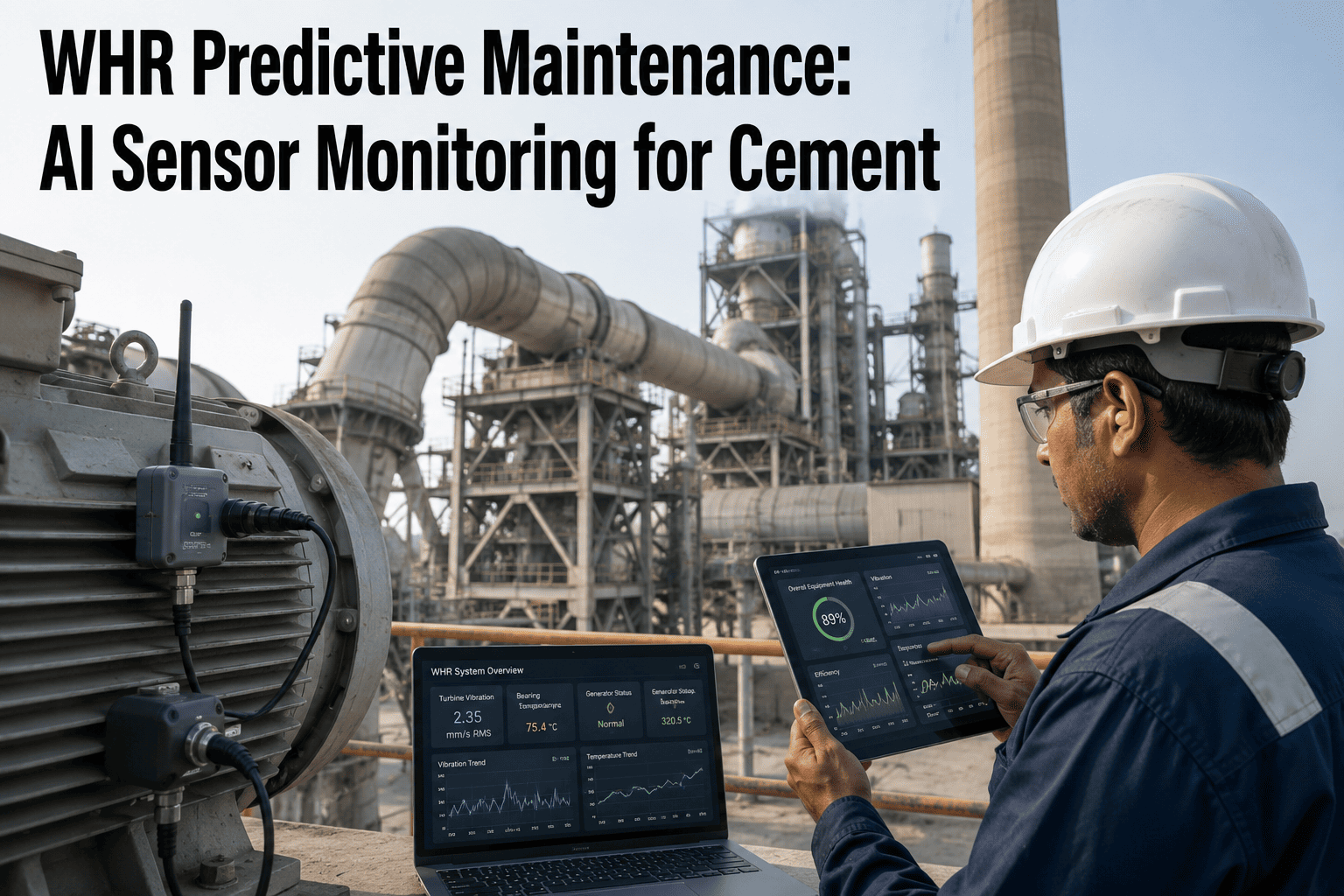
The three components that account for the overwhelming majority of unplanned conveying downtime are the blower package, the diverter valve bank, and the pipeline itself, particularly at bends. iFactory's predictive maintenance layer instruments all three with a consistent set of sensors and builds a single health score per conveying line, so a control room operator sees one number instead of a wall of disconnected pressure and current readings.
This matters more in cement than in almost any other industry because conveying lines here are unusually long, unusually abrasive, and unusually central to plant throughput at the same time. A single fly ash or cement conveying route can serve as the only path between a mill and a silo, or between a silo and the packing plant, meaning a blockage anywhere along that route does not just slow one process — it stops the entire downstream chain until the line is cleared. Unlike a conveyor belt, where a blockage is usually visible and accessible, a pneumatic line blockage is hidden inside sealed pipe, often routed through elevated structural steel or underground trenches, which is exactly why the clearance process takes hours rather than minutes even once the location is identified.
Three Components, Three Failure Signatures
Each component in the conveying chain fails differently, and each needs a different set of sensors and thresholds. Building one generic "vibration alarm" across all three misses the specific physics of how each part actually degrades.
Blower Package
Roots-type and screw blowers lose volumetric efficiency as rotor clearances open up from abrasive dust ingestion. iFactory tracks discharge pressure against motor current draw — a widening gap between the two is the earliest sign of internal slip, typically visible 4-6 weeks before a blower can no longer hold conveying line pressure.
Diverter Valve Bank
Flap and rotary diverter valves seal with a rubber or ceramic-lined seat that erodes with every cycle. A worn seat lets material leak into the wrong branch, contaminating product or slowly filling a line that should be idle. Cycle-count tracking combined with actuator torque monitoring flags seats approaching end of life before a misroute happens.
Pipeline & Elbows
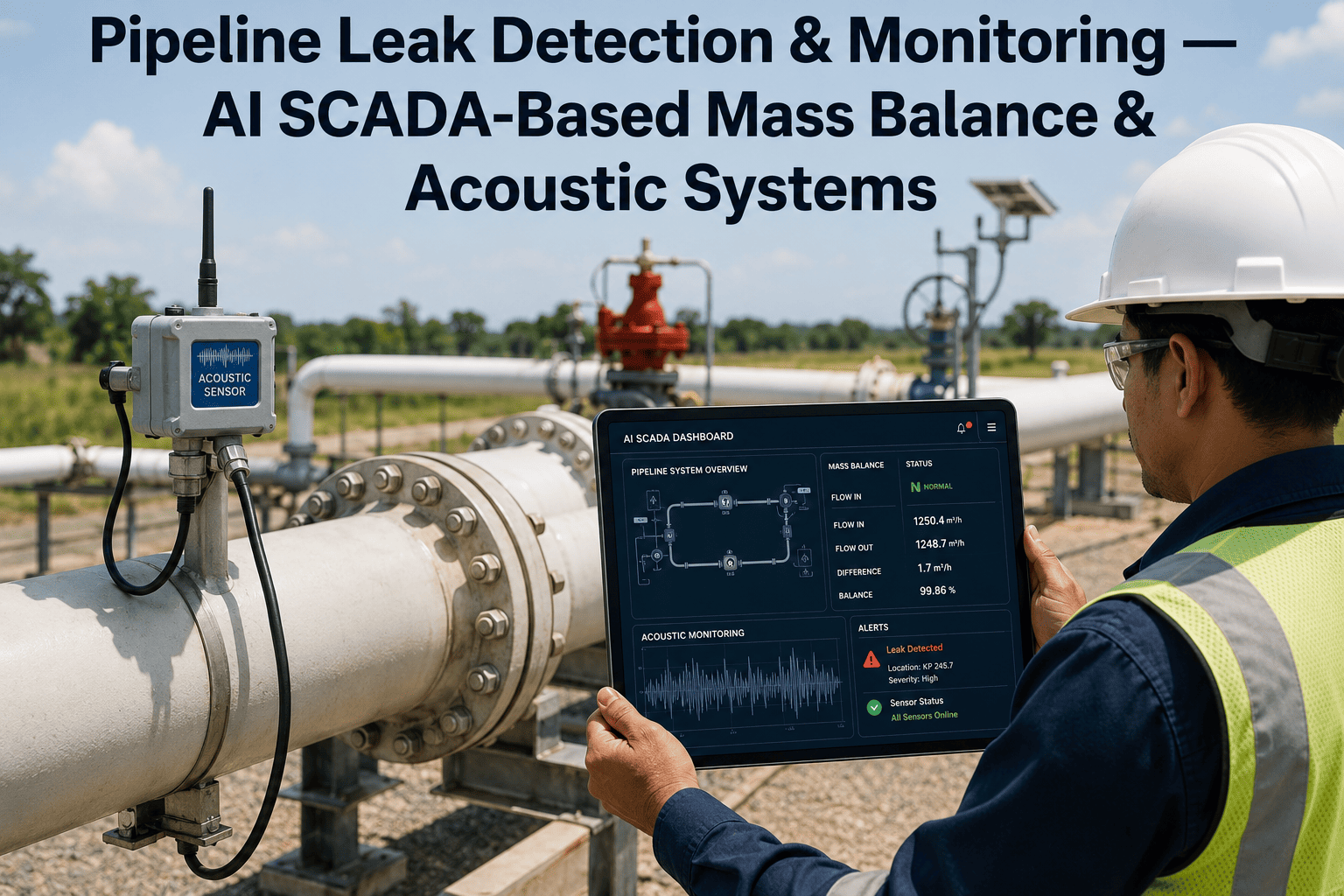
Erosive wear concentrates at bends, tees, and any point where material changes direction at velocity. Wall-thickness loss is invisible from outside the pipe until it perforates. Acoustic emission sensors clamped to high-wear elbows detect the change in particle-impact sound signature that precedes a through-wall leak.
Reading the Line: Symptom, Root Cause, and Predictive Signal
Most conveying problems present as the same downstream symptom — reduced throughput or a line trip — with several possible root causes. The table below is the diagnostic reference iFactory builds into its conveying-line dashboard, mapping what the operator sees to what is actually happening inside the pipe.
| Observed Symptom | Likely Root Cause | Predictive Signal to Track |
|---|---|---|
| Line pressure climbing slowly over shift | Partial blockage building at an elbow | Segment-wise differential pressure trend |
| Blower current rising, pressure flat | Rotor clearance wear reducing volumetric output | Current-to-pressure ratio drift |
| Wrong silo receiving material | Diverter valve seat leakage | Actuator torque and position feedback delay |
| Sudden pressure spike then drop | Full blockage forming and clearing intermittently | Pressure variance / standard deviation over rolling window |
| Localized fine dust leakage at flange | Wall perforation from erosive wear | Acoustic emission amplitude at that segment |
| Airlock feeder tripping on overload | Rotor-to-housing clearance closed by material buildup | Feeder motor torque trend |
See Your Conveying Line's Health Score in a Live Demo
We'll walk through a blower, diverter valve, and pipeline segment from a plant similar to yours and show exactly what an early-warning alert looks like before it becomes a blocked line.
Dilute Phase vs Dense Phase: Different Wear, Different Monitoring
Not every conveying line wears the same way, and the monitoring strategy has to match the conveying mode. Dilute phase systems move material at high velocity suspended in a large volume of air, which keeps the line from blocking easily but accelerates erosive wear at every bend because particles strike pipe walls at high speed and shallow angle. Dense phase systems move material at much lower velocity in slugs or plugs with a smaller air volume, which dramatically reduces pipe erosion but increases the risk of a full blockage if the blower cannot maintain the pressure needed to keep the material plug moving. A plant running dilute phase conveying for fly ash or cement should weight its monitoring investment toward acoustic emission sensors at elbows, while a dense phase system for abrasive raw meal should weight toward blower pressure and current monitoring, since a dense phase blockage is a much more disruptive event than the gradual wear a dilute phase line experiences.
Many cement plants run both conveying modes simultaneously across different material streams without realizing the two need fundamentally different sensor prioritization. iFactory's line health scoring adjusts its weighting automatically based on which conveying mode a given line uses, so a dense phase raw meal line gets proportionally more weight on blower pressure stability while a dilute phase fly ash line gets more weight on elbow wear tracking.
What Blockage Costs a Cement Plant
A blocked pneumatic line is rarely a five-minute fix. Once material packs solid in a horizontal or vertical run, the standard response is to isolate the section, open access points, and physically break up the blockage — a job that routinely takes two to six hours depending on line length and location, and that exposes the crew to a confined-space and dust-exposure task that plants would prefer to avoid entirely. During that window, the receiving silo is starved, which can cascade into a kiln feed interruption, a packing line stoppage, or a mill that has to be slowed to match reduced material availability.
Beyond the direct clearance labour, repeated blockages accelerate wear on everything upstream — the blower runs against higher back-pressure, seals see more pressure cycling, and diverter valves cycle more often as operators reroute around a blocked branch. Plants that instrument all three components typically report that unplanned line trips fall by roughly 80% within the first year, simply because the two or three failure modes that caused most events are caught while they are still a maintenance work order rather than a shutdown.
There is also a safety dimension that rarely makes it into the cost conversation but should. Manually clearing a blocked conveying line typically requires opening inspection ports or flanges on a pressurized system carrying fine, abrasive dust, sometimes at height or in confined access points within the conveying gallery. Every blockage cleared manually is an exposure event for the crew involved, and reducing the frequency of these events through predictive monitoring is as much a safety improvement as it is a production and cost improvement — a point that tends to resonate strongly with EHS teams evaluating where to prioritize monitoring investment across a plant's many mechanical systems.
Building the Programme: Four Steps
Map the Line and Identify High-Wear Points
Walk the physical pipe run with maintenance and mark every elbow, tee, and reducer. Rank each by conveying velocity and material abrasiveness — these are your acoustic emission sensor placement priorities.
Instrument Blower and Diverter Valve Baselines
Install current and pressure transducers on the blower and torque/position feedback on each diverter valve actuator. Run for two to three weeks to establish a healthy baseline before setting alert thresholds.
Build the Composite Line Health Score
iFactory combines blower efficiency drift, valve torque trend, and segment-wise acoustic and pressure readings into one composite score per conveying line, visible on the control room dashboard alongside kiln and mill KPIs.
Route Alerts to Auto-Generated Work Orders
When a component crosses its threshold, a work order is generated automatically with the specific part, location, and recommended action — closing the loop from sensor reading to maintenance execution without manual triage.
Maintenance Task Checklist by Frequency
Predictive monitoring reduces reliance on manual checks, but it works best layered on top of a disciplined baseline routine rather than replacing it entirely. The table below is the task cadence iFactory recommends for conveying lines even after sensors are installed, since a few checks — visual inspection for dust leakage, air supply moisture drain-down — are still faster and more reliable done by hand than through instrumentation.
| Frequency | Task | Why It Still Matters With PdM |
|---|---|---|
| Daily | Visual walk-down for dust leakage at flanges and glands | Catches gasket failures that sensors don't directly monitor |
| Daily | Check blower inlet air filter differential pressure | Clogged filters reduce blower efficiency independent of internal wear |
| Weekly | Drain moisture from compressed air supply to diverter actuators | Moisture accelerates actuator seal wear between torque readings |
| Weekly | Review composite line health score trend with maintenance planner | Turns sensor data into a scheduled work order before threshold breach |
| Monthly | Calibration check on acoustic emission and pressure transducers | Keeps predictive thresholds accurate as sensors age |
| Quarterly | Manual wall-thickness spot check at top 3 highest-wear elbows | Cross-validates acoustic emission trend against physical measurement |
Frequently Asked Questions
Can this be retrofitted onto an existing conveying system without replacing the blower or valves?
Yes. The sensors used for this programme — current transducers, clamp-on acoustic emission sensors, and actuator torque monitors — are all non-invasive and install on existing equipment without process interruption. Most plants complete instrumentation of a full conveying line, including blower, diverter bank, and the highest-wear pipe segments, within a single planned maintenance window. There is no need to replace the blower, the valves, or any section of pipe to begin collecting predictive data; the retrofit simply adds a monitoring layer on top of what is already installed. You can review the full sensor list and installation process with our team through support.
How early does the system detect blower wear compared to a manual pressure check?
A manual daily pressure check typically only catches blower degradation once it has already crossed a visible threshold, often within days of a trip. Continuous current-to-pressure ratio tracking, by contrast, detects the early drift in volumetric efficiency four to six weeks before the blower would fail a manual check, because the ratio moves gradually and consistently as rotor clearances open, well before the absolute pressure reading itself looks abnormal. That lead time is what allows maintenance to schedule a rebuild during a planned stop rather than react to a trip mid-shift.
Does diverter valve monitoring prevent product contamination, not just downtime?
Yes, and for many plants this is the more valuable outcome. A diverter valve with a worn seat can leak material into the wrong branch well before it fails outright, silently blending a small percentage of one product into another silo over days or weeks. Actuator torque and position feedback monitoring catches the seat wear that causes this leakage long before it becomes a full valve failure, protecting product quality and avoiding the costly process of identifying and isolating a contaminated silo batch after the fact.
What happens to the acoustic emission sensors if we reroute the pipeline later?
The clamp-on acoustic emission sensors are not permanently bonded to the pipe and can be relocated to a new high-wear point in under an hour if a line is rerouted, replaced, or resized. Because the underlying analysis is based on the acoustic signature of particle impact rather than a fixed calibration to one specific pipe segment, the sensor and its associated alert thresholds can be reapplied to a new elbow or tee with only a short recalibration period rather than a full reinstallation project.
How does this integrate with our existing CMMS or SAP PM system?
iFactory's predictive maintenance module integrates bi-directionally with SAP PM and most standard CMMS platforms, so an alert crossing threshold on a conveying line component automatically generates a work order in your existing system rather than a separate, disconnected notification. Maintenance teams continue working entirely inside the CMMS or SAP interface they already know, while the underlying trigger for each work order now comes from real-time sensor data instead of a fixed calendar interval or a reactive breakdown call. Our support team handles the integration setup during onboarding.
Give Your Conveying Lines an Early-Warning System
Book a 30-minute walkthrough and we'll show you what blower, diverter valve, and pipeline monitoring looks like on a system similar to yours.