Bridge Scour Countermeasures and Monitoring per FHWA HEC 23
By Grace on June 18, 2026
Scour is the leading cause of bridge failures in the United States, accounting for approximately 60% of all hydraulic-related bridge collapses. The FHWA Hydraulic Engineering Circular No. 23 provides the definitive design guidance for scour countermeasures — from riprap and articulating concrete block systems to real-time sonar monitoring and fixed instrumentation. For bridge engineers, hydraulic specialists, and state DOT scour program managers, understanding the HEC-23 countermeasure framework, the three-category classification system, and the Plan of Action requirements for scour critical bridges is essential for protecting infrastructure and maintaining NBIS and SNBI compliance.
FHWA HEC-23 · Scour Countermeasures · Real-Time Monitoring · Plan of Action
Scour Causes 60% of Bridge Failures. HEC-23 Countermeasures and Real-Time Monitoring Are Your First Line of Defense.
iFactory helps state DOTs and bridge agencies implement HEC-23 compliant scour countermeasure programmes, deploy real-time scour monitoring instrumentation, and develop risk-based Plans of Action for scour critical bridges in their inventory.
Of all US bridge failures are caused by hydraulic scour — more than earthquakes, overloading, collision, and material degradation combined.
3
Countermeasure categories: physical armour, hydraulic modification, and monitoring instrumentation — each with specific HEC-23 design guidelines.
14
HEC-23 Design Guidelines covering riprap, articulating concrete block, grout-filled mattresses, gabions, and countermeasures for piers and abutments.
900+
Scour critical bridges monitored in a single state using real-time sonar sensor networks deployed through HEC-23 monitoring countermeasure frameworks.
The HEC-23 Framework: Three Hydraulic Engineering Circulars That Govern Bridge Scour Management
The FHWA bridge scour programme is built on three companion Hydraulic Engineering Circulars that together cover the full lifecycle of scour management: evaluation, stream stability assessment, and countermeasure selection and design. HEC-23 specifically addresses the third pillar — providing design guidance for countermeasures that prevent, delay, or reduce the severity of scour at bridges. Understanding how HEC-23 relates to HEC-18 and HEC-20 is the first step in applying the correct countermeasure framework to a given bridge scour problem.
HEC-18
Evaluating Scour at Bridges
The primary technical reference for calculating scour depths at bridge piers, abutments, and contraction zones. HEC-18 provides the pier scour equation, contraction scour methodology, and abutment scour prediction procedures used by hydraulic engineers nationwide. Scour depth estimates from HEC-18 directly inform the design of countermeasures selected through HEC-23 and determine whether a bridge is classified as scour critical under the SNBI coding framework. The most recent equation revisions for coarse-bed pier scour are incorporated into the FHWA Hydraulic Toolbox for efficient analysis.
HEC-20
Stream Stability at Highway Structures
Provides the methodology for assessing stream channel stability and identifying channel instability mechanisms that contribute to scour. HEC-20 covers riparian vegetation assessment, channel evolution models, and stream classification systems that help engineers determine whether a scour problem is caused by local pier scour, contraction scour, or broader channel degradation. This distinction determines which category of countermeasure — pier protection, channel armour, or hydraulic modification — is appropriate for the specific site conditions.
HEC-23
Bridge Scour Countermeasures
Consolidates countermeasure experience, selection methodology, and design guidance into 14 Design Guidelines covering physical armour systems, hydraulic countermeasures, and monitoring instrumentation. HEC-23 Volume 1 covers countermeasure selection and management strategy; Volume 2 provides the detailed design guidelines for each specific countermeasure type. The document also outlines the Plan of Action framework for scour critical bridges and provides guidance on fixed and portable scour monitoring instrumentation.
The Three Categories of Scour Countermeasures per HEC-23
HEC-23 organises countermeasures into three categories. The selection depends on the scour mechanism, site hydraulic conditions, bridge foundation type, and agency resource constraints. Many scour critical bridges require a combination of countermeasure categories within a single Plan of Action.
HEC-23 Countermeasure Categories — Physical, Hydraulic, and Monitoring
Category 1 — Physical
Armour and Structural Countermeasures
Physical countermeasures resist erosive forces directly at the pier, abutment, or channel bed. They include rock riprap (the most common countermeasure type used at 50% or more of sites), partially grouted riprap, articulating concrete block systems, gabion mattresses, grout-filled mattresses, and grout-filled bags. Physical countermeasures are designed to remain stable under design flood conditions and require a properly designed filter layer to prevent soil loss through the armour openings. The HEC-23 Design Guidelines 8 through 14 provide specific design procedures for each physical countermeasure type, including rock sizing equations, apron dimensions, filter requirements, and construction specifications.
DG8–DG14: Riprap, ACB, gabions, grout mats — design procedures for each armour type.
Category 2 — Hydraulic
Flow Modification Countermeasures
Hydraulic countermeasures modify the flow pattern approaching the bridge to reduce the erosive forces acting on the foundation. They include guide banks, spur dikes, check dams, stream barbs, and bank revetment that redirect flow away from piers and abutments or reduce the contraction ratio at the bridge opening. These countermeasures address the cause of scour rather than armouring against its effects. They require hydraulic analysis using HEC-RAS or 2D hydraulic models to evaluate the flow redirection effectiveness and to ensure that redirecting flow does not create scour problems at adjacent bridge elements or property.
Hydraulic countermeasures require stream stability analysis per HEC-20 before selection.
Category 3 — Monitoring
Instrumentation and Inspection Countermeasures
Monitoring countermeasures do not prevent scour but provide early warning when scour reaches critical depths. They include fixed instrumentation (sonar sensors permanently installed at piers, accelerometers on bridge superstructure, water level sensors), portable instrumentation (handheld sonar, tethered floatation-based systems, remote-controlled vessels with single-beam sonar), and visual inspection during flood events. Monitoring is the appropriate countermeasure for bridges where the risk is moderate, where physical countermeasures are not feasible due to site constraints, or as a temporary measure while permanent physical countermeasures are designed and constructed. Real-time monitoring systems with cloud-based data processing can transmit scour depth readings and alerts to agency personnel during flood events.
Monitoring countermeasures are documented in HEC-23 Chapter 9 and Design Guideline formats.
Physical Countermeasure Design Guidelines: Riprap, ACB, Grout-Filled Mattresses, and Gabions
HEC-23 Volume 2 provides detailed design guidelines for each physical countermeasure type. Each Design Guideline includes rock or unit sizing procedures, layer thickness requirements, filter criteria, apron geometry specifications, and construction quality control provisions. Selection among the available countermeasure types depends on hydraulic conditions, availability of materials, environmental permitting constraints, and lifecycle cost.
DG11 / DG14 — Rock Riprap
Riprap at Bridge Piers and Abutments
Riprap is the most widely used scour countermeasure in the United States, applied at bridge piers (DG11) and abutments (DG14). Design consists of determining the median rock diameter D50 required to resist the design velocity and shear stress. HEC-23 specifies a standard riprap gradation, a minimum layer thickness of 1.5 times the maximum rock diameter or 2 times D50, and a geotextile or granular filter to prevent soil loss through the armour layer. For piers, the riprap apron extends horizontally from the pier face a distance determined by the flow depth and pier width, with a minimum extent of 2 times the pier width. Flush-mounted aprons are preferred over mounded riprap, which HEC-23 advises against due to turbulence generation at the mound edges.
Rock sizing per HEC-23: D50 based on approach velocity, flow depth, pier shape, and angle of attack.
DG12 — Partially Grouted Riprap
Partially Grouted Riprap for Piers
Partially grouted riprap allows the use of smaller rock sizes while maintaining stability by adding grout to fill some of the void spaces. The grout is applied to the upper portion of the riprap layer, leaving the lower portion ungrouted to maintain flexibility and drainage. This countermeasure is appropriate where the required D50 for loose riprap is not economically available or where minimum layer thickness constraints favour a more stable armour unit. Design guidance covers grout application rate, penetration depth requirements, and filter compatibility. PGR has been successfully applied as a remedial countermeasure for scour critical bridges where site access or hydraulic conditions limit conventional riprap placement.
PGR enables smaller rock with increased stability. Environmental permitting requirements vary by state.
DG8 — Articulating Concrete Block
Articulating Concrete Block Systems
ACB systems consist of individual concrete blocks connected by cables or geotextile that form a continuous flexible armour mat. The blocks articulate with the streambed while maintaining coverage, making ACB suitable for sites where channel bed degradation would leave a rigid countermeasure unsupported at its edges. HEC-23 DG8 provides design procedures for block thickness, filter layer requirements, edge treatment details, and cable connection specifications. ACB systems are installed with the blocks placed on a geotextile filter fabric and tied together at the edges to prevent undermining at the mat perimeter.
ACB systems maintain armour coverage during bed degradation. Placement in-the-wet requires specialised installation.
DG9 / DG10 — Grout-Filled Mattresses and Gabions
Grout-Filled Mattresses and Gabion Mattresses
Grout-filled mattresses (DG9) are continuous fabric forms filled with pumped grout to form a mattress that conforms to the streambed. Gabion mattresses (DG10) are rectangular wire mesh baskets filled with rock and laced together to form a continuous blanket. Both provide flexible armour that can accommodate differential settlement. Gabion mattresses are particularly common on the East Coast of the United States for pier protection. Design guidance in HEC-23 covers mattress thickness, filter requirements, edge anchorage, and wire mesh specifications. Gabion baskets must be constructed with wire mesh corrosion protection appropriate for the site water chemistry and service life requirements.
Gabion and grout mattress designs require wire mesh corrosion protection and proper toe anchoring.
HEC-23 Compliance · Scour Countermeasure Design · POA Development
Not Sure Which HEC-23 Countermeasure Is Right for Your Scour Critical Bridge? iFactory Helps You Select, Design, and Document the Right Approach.
iFactory supports state DOTs with HEC-23 countermeasure selection, POA development, real-time scour monitoring instrumentation deployment, and SNBI scour vulnerability coding compliance for scour critical bridge inventories.
Real-Time Scour Monitoring: Sonar Sensors, Fixed Instrumentation, and Remote Deployment
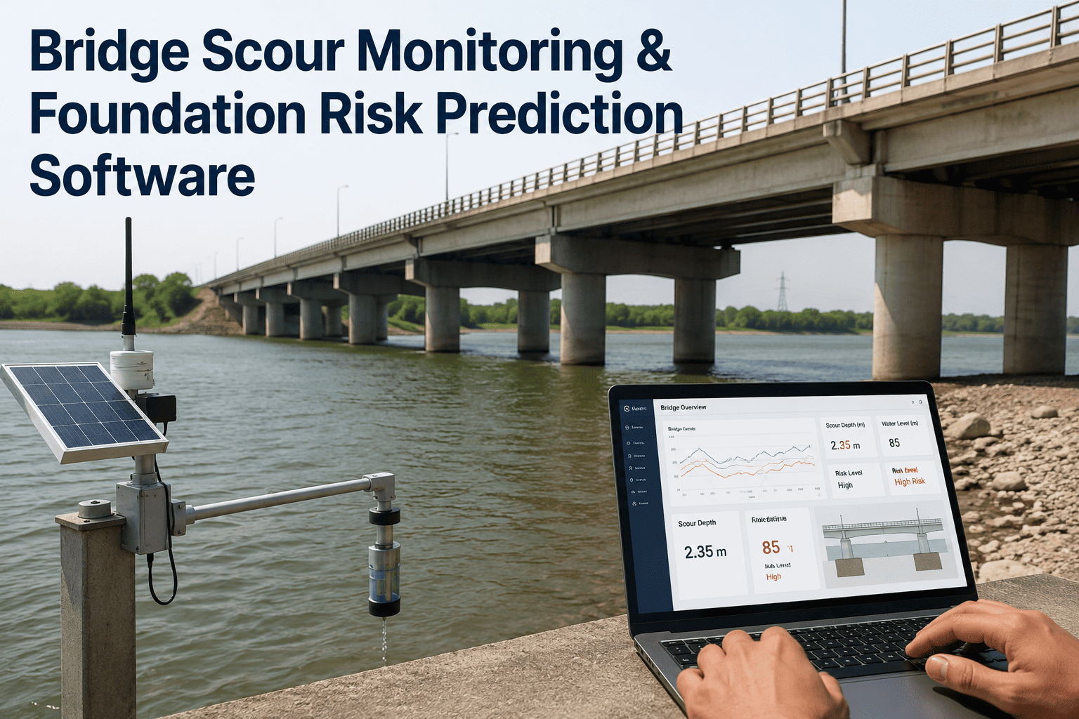
The 2025 and 2026 advancements in bridge scour monitoring have shifted the practice from periodic post-flood inspection to continuous real-time monitoring using fixed sonar sensors, accelerometers, and cloud-based data processing. HEC-23 Chapter 9 provides guidance on monitoring instrumentation selection and deployment, and recent USGS and state DOT studies have demonstrated the effectiveness of real-time sonar monitoring at scour critical bridges. For agencies managing hundreds of scour critical bridges, real-time monitoring is transitioning from a pilot technology to an operational standard.
Scour Monitoring Technologies — Deployment Characteristics and Data Outputs
Fixed Sonar Sensors
Permanently mounted downward-facing sonar transducers installed on pier faces or bridge superstructure. Measure streambed elevation at programmed intervals (typically 15 to 30 minutes). Data transmitted via cellular or satellite modem to cloud-based platforms. Provide continuous bed elevation records that capture scour progression during flood events. USGS studies at Idaho scour critical sites demonstrated effective real-time local pier scour monitoring using fixed sonar sensors. Require periodic maintenance for sensor cleaning and debris removal.
Measurement: Streambed elevation. Interval: 15–30 min. Alert: Configurable scour threshold.
Portable and Rapid Deployment Systems
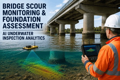
Handheld or tethered sonar units deployed from bridge decks during flood events. Include floatation-based single-beam sonar systems that can be cast from the bridge deck and retrieved after measurement. Also include remote-controlled vessels mounted with single-beam sonar for post-flood bathymetric surveys. These systems are lower-cost than fixed installations and can be deployed across multiple bridges by a single inspection team. They provide measurement data during and immediately after flood events when direct inspection from a boat or wading is dangerous.
Measurement: Scour depth. Deployment: Per event. Cost: Low relative to fixed installations.
Integrated Sensor and Alert Systems
Combine sonar depth sensors with accelerometers for pier vibration monitoring, water level sensors, and weather stations. Data flows through cloud-based platforms such as Scour View that provide real-time visualisation, automated alert triggers when scour reaches critical elevations, and integration with BridgeWatch flood monitoring systems. Machine learning applied to accelerometer data can distinguish between flood and non-flood conditions and detect anomalous vibration patterns associated with scour progression. These integrated systems enable risk-based deployment of inspection teams during flood events.
We deployed fixed real-time sonar sensors at three scour critical bridge sites in Idaho and compared the observed pier scour depths against HEC-18 equation estimates. The real-time data confirmed that the pier scour equation was conservative for our coarse-bed conditions — the observed scour was consistently less than predicted. This gave us the evidence to recode those bridges from scour critical to stable, eliminating the POA requirement and focusing monitoring resources on bridges with higher actual risk. Without the real-time monitoring data, those bridges would have remained coded as scour critical indefinitely. The sonar data gave us the engineering basis to change the classification.
— USGS Hydrologist — Real-Time Pier Scour Monitoring Study, Idaho Water Science Center
Plans of Action for Scour Critical Bridges: What HEC-23 and NBIS Require
Every bridge classified as scour critical under the NBIS (23 CFR 650 Subpart C) must have a Plan of Action. The POA specifies the management strategy for the scour critical bridge, including the countermeasure selected, monitoring procedures, closure triggers, detour routes, and responsible parties. HEC-23 provides the framework for developing POAs that are consistent with FHWA policy and appropriate for the risk level of each bridge.
Plan of Action Elements — What Every Scour Critical Bridge POA Must Include
Element 1
Scour Evaluation Summary
HEC-18 scour depth estimates at each pier and abutment. Scour critical elevation identified for each foundation element. Hydrologic and hydraulic data including design flood discharge and water surface elevation. Angle of attack, contraction ratio, and bed material characteristics documented.
Element 2
Countermeasure Selection and Design
Selected countermeasure type with HEC-23 Design Guideline reference. Design parameters including rock D50, apron dimensions, filter specification, or monitoring instrumentation type and installation details. Construction schedule for physical countermeasures or installation timeline for monitoring equipment.
Element 3
Monitoring and Closure Triggers
Scour alert elevation and scour critical elevation for each pier or abutment. Monitoring method and frequency. Flood event monitoring protocol. Bridge closure criteria and notification procedures. Designated responsible parties for monitoring, decision-making, and closure execution. Detour route plan.
Element 4
POA Review and Update Schedule
POA review frequency and responsible reviewer. Condition triggering unscheduled POA review. Documentation of countermeasure condition inspections. SNBI coding update protocol when scour vulnerability changes. Linkage to NBIP oversight and risk-based prioritisation.
SNBI Scour Coding: B.AP.03, B.C.11, and B.AP.04
The SNBI includes three scour-related data items that every bridge inspection must report. The scour vulnerability code (B.AP.03) classifies the bridge's susceptibility to scour. The scour condition rating (B.C.11) documents the observed scour condition at the time of inspection. The scour plan of action code (B.AP.04) tracks whether a POA has been developed. These three items together provide FHWA and state DOTs with a national picture of scour risk and POA implementation status. Accurate coding depends on proper scour evaluation per HEC-18, countermeasure documentation per HEC-23, and POA completion per NBIS requirements.
Conclusion
Scour remains the most significant hydraulic threat to bridge infrastructure in the United States, responsible for more failures than all other causes combined. The FHWA HEC-23 framework provides the engineering tools to address this threat through a structured countermeasure selection and design process — but the effectiveness of any countermeasure programme depends on proper scour evaluation, correct countermeasure selection for the site-specific hydraulic conditions, and consistent inspection and monitoring after installation.
The 2025 and 2026 developments in real-time scour monitoring technology are changing what is possible for state DOT scour programmes. Fixed sonar sensors, cloud-based data platforms, and ML-powered anomaly detection now enable continuous monitoring of scour critical bridges at a fraction of the cost of frequent manual inspections. Agencies that integrate real-time monitoring into their POA frameworks can detect scour progression during flood events, deploy inspection teams based on data rather than schedule, and build the engineering evidence base needed to recode bridges from scour critical to stable where the data supports it.
iFactory helps state DOTs and bridge agencies implement HEC-23 compliant scour countermeasure programmes, deploy real-time scour monitoring instrumentation, develop risk-based Plans of Action, and maintain accurate SNBI scour vulnerability coding. Book a Demo to see how our platform supports scour countermeasure documentation and POA management, or talk to an expert about a scour programme assessment for your bridge inventory.
Frequently Asked Questions
HEC-18 (Evaluating Scour at Bridges) provides the equations and methodology for calculating anticipated scour depths at piers, abutments, and channel contractions. HEC-23 (Bridge Scour and Stream Instability Countermeasures) provides the design guidance for countermeasures that protect against those calculated scour depths. In practice, you use HEC-18 first to determine how deep scour is expected to be at each bridge element, then use HEC-23 to select and design the appropriate countermeasure to resist that scour depth. The two documents are designed as companion references and are used sequentially in the scour evaluation and countermeasure design process. HEC-20 (Stream Stability at Highway Structures) is used before both to assess the stream channel context. Talk to an expert about integrating the three HEC documents into your scour programme workflow.
Real-time monitoring is appropriate as a countermeasure when the bridge presents moderate risk, when physical countermeasures are not feasible due to site constraints such as limited access or environmental permitting restrictions, or as a temporary measure while permanent physical countermeasures are designed and constructed. FHWA guidance recognises monitoring as one of three countermeasure categories, with the understanding that monitoring does not prevent scour but enables timely action when scour reaches critical depths. Bridges with monitoring as the sole countermeasure remain classified as scour critical and require a POA that specifies scour alert elevations, closure triggers, and notification procedures. For high-risk bridges with deep foundations subject to rapid scour progression during flood events, a physical armour countermeasure or foundation retrofit is typically more appropriate than monitoring alone. Book a Demo to see how iFactory supports monitoring-based POA documentation.
Selection depends on hydraulic conditions, material availability, environmental constraints, and lifecycle cost. Riprap is the most common and generally the most cost-effective option where suitable rock is available within economic haul distance. Articulating concrete block systems are preferable where the channel bed is expected to degrade over time, because the articulated blocks maintain coverage while a rigid mattress would become unsupported at its edge. Grout-filled mattresses provide an impermeable armour surface suitable for sites where seepage forces or high-velocity flow could remove material through riprap openings. Partially grouted riprap offers a middle option — smaller rock with increased stability — appropriate where D50 requirements for loose riprap exceed economically available rock sizes. HEC-23 provides a countermeasure selection matrix that guides engineers through the decision process based on flow velocity, scour depth, bed material, construction access, and environmental factors. Talk to an expert about a countermeasure selection review for your scour critical bridges.
The SNBI requires three scour-related data items for every bridge: B.AP.03 Scour Vulnerability (a single-digit code indicating the current scour risk status), B.C.11 Scour Condition Rating (the observed scour condition at inspection), and B.AP.04 Scour Plan of Action (whether a POA exists and its status). A bridge is classified as scour critical when B.AP.03 codes indicate that the foundation is unstable due to observed or calculated scour. All scour critical bridges must have a POA documented. The POA does not change the classification — a bridge with a POA remains scour critical until physical countermeasures or foundation improvements are completed and the foundation is recoded based on re-evaluation. Monitoring countermeasures documented in a POA do not change the classification either. Recoding from scour critical to stable requires a scour re-evaluation demonstrating that the calculated scour depth no longer threatens foundation stability, supported by field observations or real-time monitoring data where available. Book a Demo to see how iFactory integrates SNBI scour coding with POA tracking.
Real-time sonar monitoring data provides direct field measurement of scour depth during flood events, which can be compared against the HEC-18 predicted scour depths that originally determined the scour critical classification. If multiple flood events with discharges approaching the design flood produce observed scour depths consistently less than the predicted depths, the data may support a re-evaluation that recodes the bridge from scour critical to stable. USGS studies in Idaho demonstrated this application — real-time pier scour monitoring data showed that the coarse-bed pier scour equation was conservative for the monitored sites, and the data provided the engineering basis for recoding. The key requirement is that the monitoring data must capture bed elevation during a flood event of sufficient magnitude to test the scour prediction. Agencies should document the monitoring period, the flood events captured, the comparison between observed and predicted scour, and the engineering analysis supporting the recode recommendation. Talk to an expert about developing a sonar monitoring plan for scour critical recode evaluation.
HEC-23 requires a filter layer under all riprap scour countermeasures to prevent soil loss through the armour openings. The filter can be either a granular filter (one or more layers of graded aggregate meeting specified permeability and retention criteria) or a geotextile filter fabric. The filter must satisfy two primary criteria: retention (the filter openings must be small enough to prevent the underlying soil from washing through) and permeability (the filter must be permeable enough to prevent hydrostatic pressure buildup beneath the armour layer). For geotextile filters, HEC-23 references AASHTO M 288 specifications. For granular filters, the filter-to-base soil ratio criteria are provided in the design guidelines as a function of D15 filter / D85 base soil and D15 filter / D15 base soil ratios. Geotextile sand containers have been demonstrated as a proven technique for placing a filter under water for both riprap and partially grouted riprap installations. Improper filter design is a common cause of riprap countermeasure failure. Book a Demo to see how iFactory documents filter design specifications for HEC-23 compliance.
Scour Is the Leading Cause of Bridge Failure in the US. Every Scour Critical Bridge Needs a Compliant Plan of Action. Get a Free Scour Programme Assessment.
iFactory helps state DOTs implement HEC-23 scour countermeasure programmes, deploy real-time sonar monitoring, develop risk-based POAs, and maintain SNBI scour vulnerability coding for scour critical bridge inventories of any size.