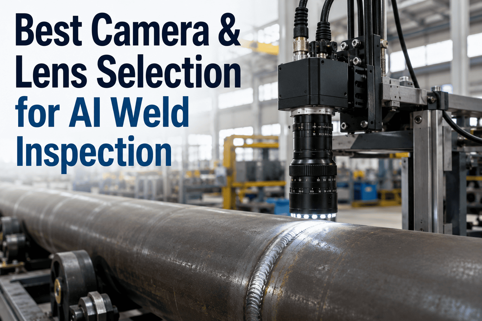
An AI weld inspection model is only as good as the image it's given to analyze, and no amount of algorithmic sophistication can recover detail that a poorly matched camera and lens never captured in the first place. Pixel resolution, field of view, and working distance aren't secondary specs to sort out after the model is built — they define the ceiling of what the model can ever detect, whether that's a hairline crack or a subtle undercut groove. Getting this selection right from the start is exactly the kind of setup work iFactory's deployment team walks through with every weld inspection installation.
Why Camera Selection Determines Model Accuracy Before Training Even Starts
It's tempting to treat camera and lens selection as a hardware procurement detail separate from the AI model itself, but the two are inseparable. A model trained to detect a 0.3 millimeter undercut groove needs enough pixels covering that groove to physically distinguish it from surrounding weld texture — no amount of training data or model architecture can manufacture detail that was never captured in the raw image.
This is where a surprising number of vision deployments underperform expectations, not because the underlying detection model is weak, but because the imaging setup upstream of it wasn't sized correctly for the defect scale the application actually requires. Getting the fundamentals right — sensor resolution, field of view, working distance, and lighting — is what determines whether the model gets a fair chance to succeed.
The Three Numbers That Actually Drive Lens Selection
Every lens selection decision comes down to the relationship between field of view, sensor size, and working distance. Get these three numbers right for your specific weld geometry, and the camera and lens choice follows logically from there.
Matching Pixel Resolution to the Defect You Need to Catch
A general rule in machine vision is to size pixel resolution so that the smallest defect you need to detect spans several pixels across its shortest dimension, not just one — a single pixel touching a defect edge is far too easy for noise or lighting variation to obscure entirely.
| Target Defect | Typical Feature Size | Recommended Resolution |
|---|---|---|
| Surface porosity | 0.3 – 1.0 mm | ≤ 0.1 mm per pixel |
| Undercut groove | 0.25 – 1.0 mm depth | ≤ 0.08 mm per pixel |
| Surface cracks | 0.1 – 0.5 mm width | ≤ 0.05 mm per pixel |
| Spatter distribution | 1.0 – 3.0 mm | ≤ 0.2 mm per pixel |
| Weld profile / bead width | Full joint width | ≤ 0.15 mm per pixel |
Notice that fine surface cracks demand the tightest resolution of the group, which is exactly why a single generic camera setup rarely covers every defect type equally well — a system tuned for crack detection is often over-specified for spatter monitoring, and vice versa.
Choosing the Right Camera and Lens Category for Weld Inspection
Beyond resolution, the physical category of camera and lens matters for how well the system holds up in a welding environment specifically — heat, arc glare, and vibration all factor into a durable selection. Contact support for guidance matched to your specific welding process and cell layout.
Where Weld Vision Deployments Most Often Go Wrong
Most underperforming vision installations trace back to one of a handful of setup mistakes made before the camera was ever mounted, rather than a limitation in the detection model itself.
Why Lighting Deserves as Much Attention as the Camera
Camera and lens selection tend to get most of the attention in a vision system design conversation, but lighting is frequently the variable that determines whether a defect is actually visible in the captured frame at all. A weld pool and surrounding heat-affected zone produce their own intense light output, which can wash out subtle surface features unless the imaging setup accounts for it directly, either through filtering, timed capture windows, or supplementary directional lighting that highlights surface texture rather than getting overwhelmed by arc glow.
Directional or grazing-angle lighting is particularly effective for surface defects like undercut and porosity, since it creates shadow contrast along the groove or pit edges that a straight-on light source would largely wash away. Cracks, being extremely thin, benefit from similar grazing light to create enough shadow definition for the pixel resolution discussion above to actually matter — the sharpest lens and highest resolution sensor still can't resolve a defect that's lit in a way that erases its visual signature entirely.
A Practical Sequence for Specifying Your Vision Setup
Rather than starting with a camera catalog, the more reliable sequence starts with the defect itself. Define the smallest defect size you genuinely need to catch, translate that into a required pixel resolution using several pixels of margin across the defect's shortest dimension, and only then work backward through the field of view and working distance formula to identify which combination of sensor and lens actually satisfies that resolution requirement within your fixture's physical constraints.
This sequence also surfaces conflicts early, before hardware is purchased and mounted. If the working distance forced by torch clearance and the field of view required to cover the full joint together demand a resolution beyond what a reasonably priced sensor can deliver, that's a conflict worth resolving on paper — whether by adjusting fixture design, splitting coverage across two cameras, or reconsidering which defect categories that specific station is actually responsible for catching — rather than discovering it after a system is already installed and underperforming.
Getting Camera Data Into the Systems That Act on It
A perfectly specified camera and lens setup still needs a clear path from captured image to actionable output. Most weld inspection deployments feed processed results into a PLC for immediate line-level response, such as pausing a robotic weld cell on a confirmed defect, while also logging results to an MES or quality database for longer-term trend analysis. Planning this integration early — deciding what triggers an immediate stop versus what simply gets logged for later review — prevents a vision system from either flooding operators with false alarms or, worse, staying silent on issues that genuinely needed an immediate response.
This integration planning also determines camera placement and cabling requirements almost as much as the optical specifications do. A camera feeding a real-time PLC interlock needs low processing latency and a robust, interference-resistant data connection, while a camera primarily supporting offline quality trend analysis has more flexibility in how quickly its data needs to reach the downstream system.
Calibration and Maintenance Are Part of the Spec, Not an Afterthought
A camera and lens setup that's correctly specified on installation day doesn't stay perfectly calibrated forever. Weld spatter can accumulate on a lens surface over repeated cycles, gradually degrading image clarity in ways that are easy to miss until a defect goes undetected that should have been caught. Thermal cycling near the arc can also shift focus slightly over time if the housing and mounting hardware aren't rated for the sustained heat exposure of the specific welding process.
Building a routine calibration and lens-cleaning schedule into standard maintenance, rather than treating vision system upkeep as a one-time installation task, is what keeps detection accuracy consistent months and years after deployment. Shops that skip this step often see a gradual, hard-to-diagnose decline in detection sensitivity that gets mistakenly attributed to the AI model itself, when the real cause is a degraded image feeding into it.