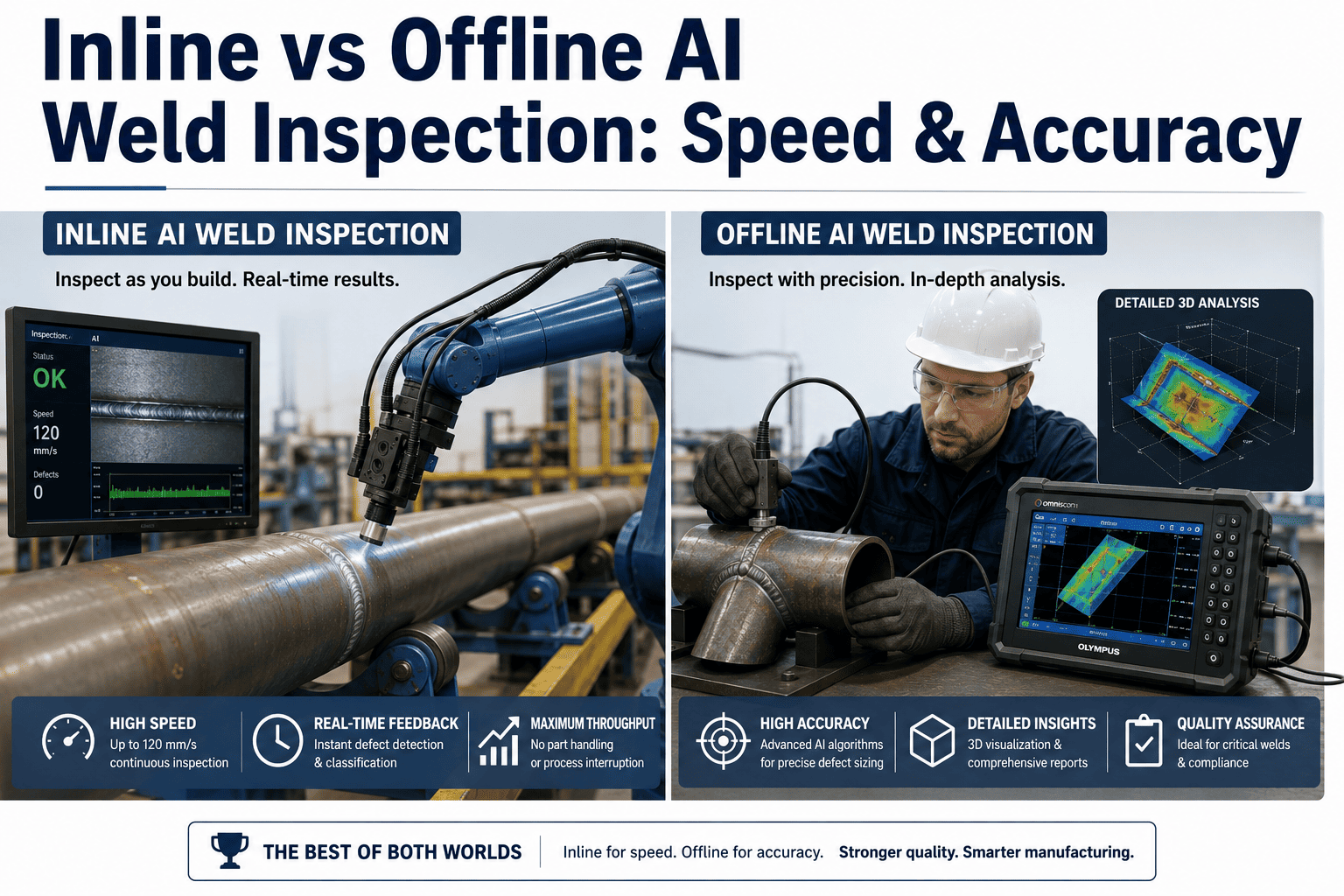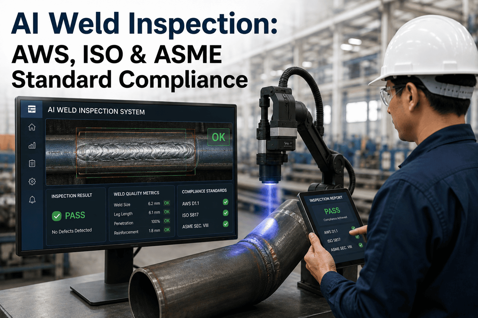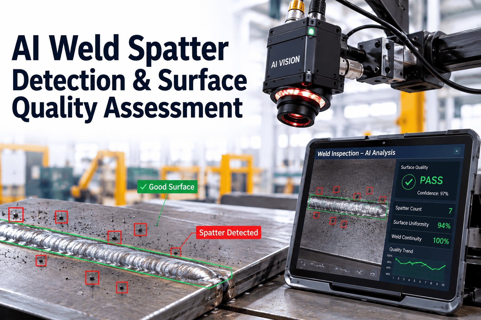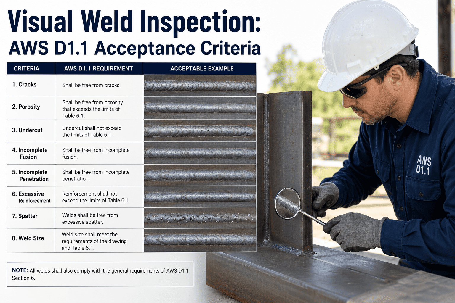
A single optical camera can tell you a weld looks right. It cannot tell you whether the root achieved full fusion, because that information is buried beneath a surface that reflects light back exactly the same way whether the joint is sound or hollow underneath. This is the ceiling every visual-only weld inspection system eventually hits — and it's why plants running the highest-consequence joints layer visual AI with thermal imaging and ultrasonic testing rather than betting the whole inspection on one sensor type. Each modality sees a different slice of what makes a weld sound, and none of them alone sees the whole picture, which is the reason fatigue-critical and pressure-retaining applications have never fully trusted a single inspection method even before AI entered the picture. See how iFactory's multi-sensor inspection architecture fuses visual, thermal, and automated ultrasonic data into a single pass or fail decision per joint.
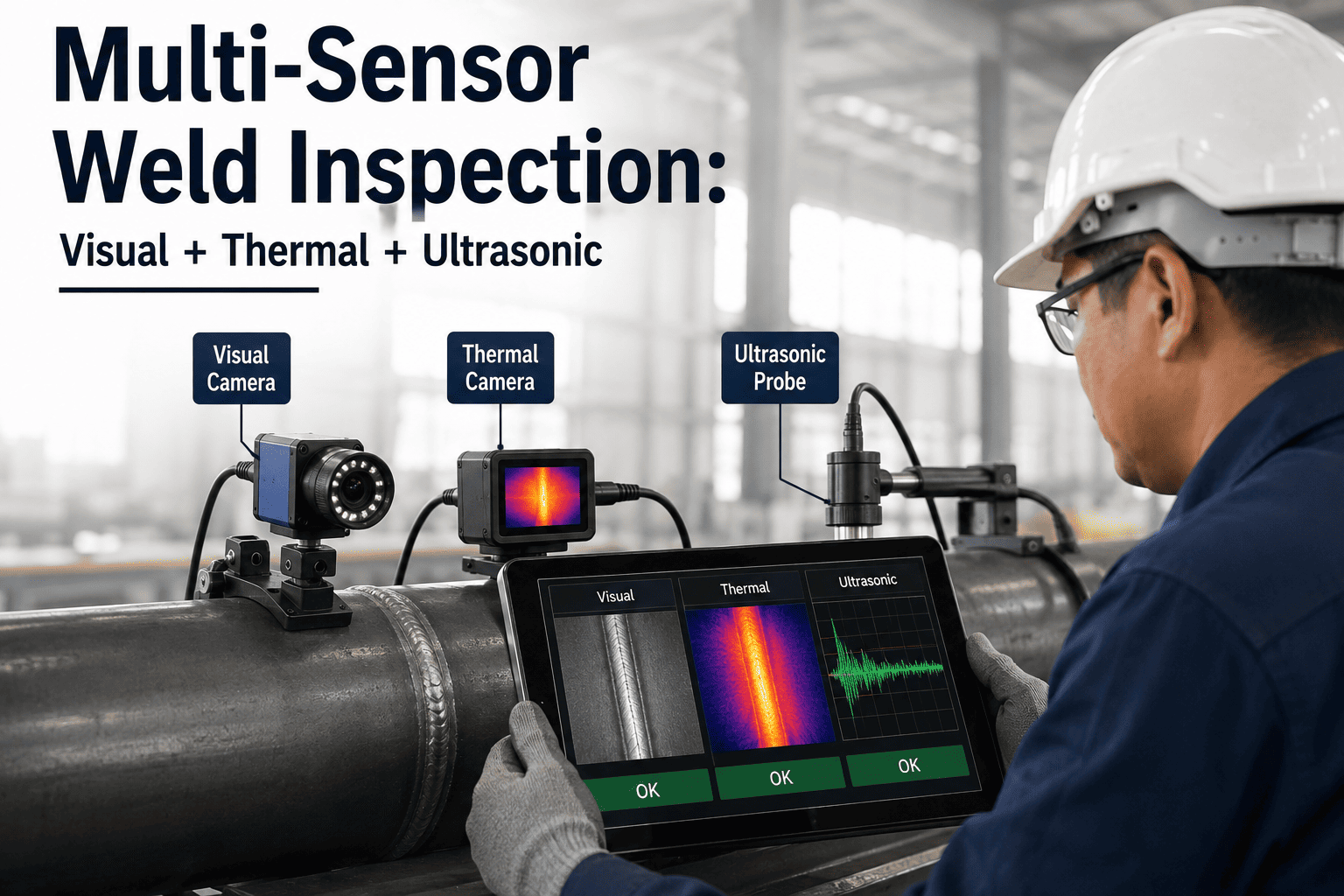
Multi-Sensor Weld Inspection: Visual + Thermal + Ultrasonic
Surface optics catch what's visible. Thermal imaging catches what's happening underneath as the weld cools. Ultrasonic testing confirms what's actually inside. Fusing all three closes the coverage gap any single sensor leaves open.
What Each Modality Cannot See on Its Own
Every inspection sensor has a physical limit to what it can detect, and that limit is set by what the sensor actually measures, not by how good the underlying AI model is. A camera measures reflected light from a surface. A thermal sensor measures infrared radiation from a heat source. An ultrasonic probe measures how sound waves travel through and reflect within a solid material. Running only one of these on a critical joint means accepting that entire categories of defect are, by definition, outside what the system can ever detect. That's a different kind of risk than a model that simply isn't trained well enough yet — training can improve a model's accuracy within its sensor's physical capability, but no amount of additional training data teaches a camera to see through solid steel, and treating a visual-only system's confidence score as equivalent to confirmed subsurface soundness is a category error that shows up eventually, usually at the worst possible time.
Every Weld Gets Screened — Not Every Weld Needs Every Sensor
Running full ultrasonic testing on every weld a plant produces isn't realistic — AUT is precise, but it's also slower and more resource-intensive than optical inspection at line speed. The practical architecture most multi-sensor deployments converge on is a funnel: broad, fast coverage from vision and thermal sensors on every weld, narrowing down to ultrasonic confirmation only on the joints that need it.
A weld that passes the visual and thermal screen with no flagged anomaly moves on without ever touching a UT probe. A weld that shows a suspicious cooling signature or a geometric deviation that correlates with known fusion-defect patterns gets routed automatically to ultrasonic confirmation, where a technician or automated UT scanner checks specifically what the earlier stages flagged rather than blind-scanning the entire joint. This is what makes full-line coverage practical on high-volume production: the expensive, slow method is reserved for the subset of welds that actually need it, identified by the fast methods running on everything. What proportion of welds actually gets routed to confirmation varies a great deal by process stability and joint criticality — a mature, well-controlled welding process on a low-criticality joint might route a small single-digit percentage of welds to AUT, while a newer process or a fatigue-critical application might route a meaningfully larger share until the thermal correlation model has enough confirmed data to tighten its routing precision. Either way, the funnel structure means AUT capacity gets spent on the welds statistically most likely to need it, rather than spread thin across a full population where most joints were never at meaningful risk in the first place.
One Coverage Gap Is All It Takes to Miss a Critical Defect
iFactory's multi-sensor platform fuses visual, thermal, and automated ultrasonic data into a single inspection decision, routing only the welds that need confirmation to NDT.
Which Sensor Actually Catches Which Defect
| Defect Type | Visual AI | Thermal Imaging | Ultrasonic Testing |
|---|---|---|---|
| Surface Porosity | Direct detection | Correlated signal | Direct detection |
| Subsurface Porosity | Not detected | Correlated signal | Direct detection |
| Incomplete Root Fusion | Not detected | Correlated signal | Direct detection |
| Surface Cracks | Direct detection | Correlated signal | Direct detection |
| Internal Cracks | Not detected | Not detected | Direct detection |
| Bead Geometry Deviation | Direct detection | Not detected | Not detected |
| Spatter | Direct detection | Not detected | Not detected |
| Cooling Rate Anomaly | Not detected | Direct detection | Not detected |
Read across any single row and the case for fusion makes itself: no single column covers every defect type, and the two rows with the highest structural consequence, subsurface porosity and incomplete root fusion, are exactly the rows where visual AI alone shows "not detected." A plant relying only on visual inspection for a fatigue-critical joint has a documented, structural blind spot on precisely the defects most likely to cause a field failure. It's worth noting that thermal imaging's "correlated signal" designation for subsurface defects isn't a weakness in the technology so much as an honest description of what infrared measurement physically provides — a correlation between a cooling-rate pattern and a known defect class, built from historical confirmed cases, rather than a direct image of the flaw itself. That's still valuable information, and often enough to justify routing a weld to confirmation, but it's a meaningfully different kind of evidence than an ultrasonic B-scan that directly images the internal structure.
What Each Sensor Actually Measures
Automated ultrasonic testing has narrowed the speed gap considerably compared to manual UT — a phased array probe on a mechanized scanner can cover a seam length far faster than a technician manually indexing a single-element probe, and AI-assisted interpretation of the resulting B-scan images is reducing the time an analyst needs to review each scan. It still isn't a real-time, every-weld method the way visual and thermal screening are, which is exactly why the funnel architecture routes it selectively rather than trying to run it on full production volume.
Not Every Application Needs the Same Sensor Stack
The right sensor combination depends on what fails if the weld is wrong. A cosmetic bracket doesn't justify the cost and cycle time of ultrasonic confirmation on every unit; a pressure vessel nozzle weld usually does, because the consequence of a missed subsurface defect is categorically different. This decision typically sits with a welding engineer or quality manager reading the governing code or the customer's engineering specification, and it's worth revisiting periodically rather than setting once — a part that was non-critical when a sensor stack was first specified can become fatigue-critical if its service application changes, and the inspection stack should track that change rather than lag behind it.
| Application Class | Typical Stack | Why |
|---|---|---|
| Non-Critical Structural | Visual AI only | Surface defects are the dominant risk; subsurface consequence is low |
| General Fabrication | Visual + thermal | Fusion-risk correlation adds confidence without full AUT cost |
| Pressure-Retaining / Fatigue-Critical | Visual + thermal + routed AUT | Subsurface soundness must be confirmed, not inferred, on flagged joints |
| Code-Mandated NDT Percentage | Full stack, AUT on mandated sample | Regulatory or code requirement sets a minimum confirmed-inspection rate |
Fusion Isn't Just Running Three Systems in Parallel
The word "multi-sensor" gets used loosely — sometimes it means three independent inspection systems reporting to three separate screens, and sometimes it means a genuinely fused decision where each modality's output feeds into a single confidence score per weld. The difference matters more than it sounds like it should, because three independent pass/fail calls create three separate places a defect can slip through a gap between systems that were never designed to talk to each other.
True fusion also changes what happens with borderline cases — the welds that don't clearly pass or clearly fail any single modality's threshold. A weld with a slightly elevated cooling-rate reading and a marginal but in-tolerance bead geometry might not trigger either system's threshold independently, but the combination of both marginal signals together is often a stronger predictor of an actual defect than either signal alone. A fused model can catch that combined pattern; three parallel systems checking their own thresholds independently generally cannot, because neither one crosses its own bar on its own. Building a genuinely fused model requires the confirmed ultrasonic results to feed back into the correlation logic over time — every AUT confirmation, pass or fail, becomes a labeled data point that either validates or adjusts the thermal and visual thresholds that routed that weld in the first place. This feedback loop is what separates a fusion system that improves with production volume from one that's calibrated once and left static, and it's usually the single biggest driver of routing precision improving over a plant's first several months running the combined system.
The mistake I see most often is treating vision AI as a replacement for ultrasonic testing instead of a filter for it. Vision is fast and it's genuinely good at what it does, but it's an optical system — it cannot see through steel, and no amount of model training changes that physical fact. What it can do is tell you which welds are worth an ultrasonic technician's time, which on a busy fabrication floor is the difference between AUT being a bottleneck and AUT being a targeted confirmation step. Once we started routing based on the thermal correlation signal instead of scanning everything, our UT throughput per shift roughly doubled without losing any coverage on the joints that actually mattered. The other change that surprised me was how much faster our root-cause investigations got once every flagged weld carried its own thermal and visual evidence alongside the UT result — instead of a technician's memory of what a weld looked like, we had the actual data attached to the finding.
Frequently Asked Questions
See Multi-Sensor Inspection Fused Into One Pass or Fail Decision
iFactory's inspection platform combines visual AI, thermal imaging, and automated ultrasonic routing so every weld gets screened and every joint that needs confirmation gets it, without slowing your line.