A production line running full speed does not stop for spatter the way it stops for a crack or a missing weld — spatter gets waved through as a cosmetic issue, caught later at paint prep or final assembly, where a grinder removes it one deposit at a time. That delay is where the real cost sits. A spatter deposit that would take two seconds to flag at the weld station takes several minutes to grind, mask, and re-inspect once the part has already moved downstream, and on a body panel bound for a Class A painted surface, missing even a handful of deposits means the whole panel gets reworked instead of the weld. AI vision measures spatter count, density, and distribution at the weld station itself, distinguishing deposits that require grinding from cosmetic surface variation that doesn't — learn more about iFactory's spatter and surface quality inspection module.
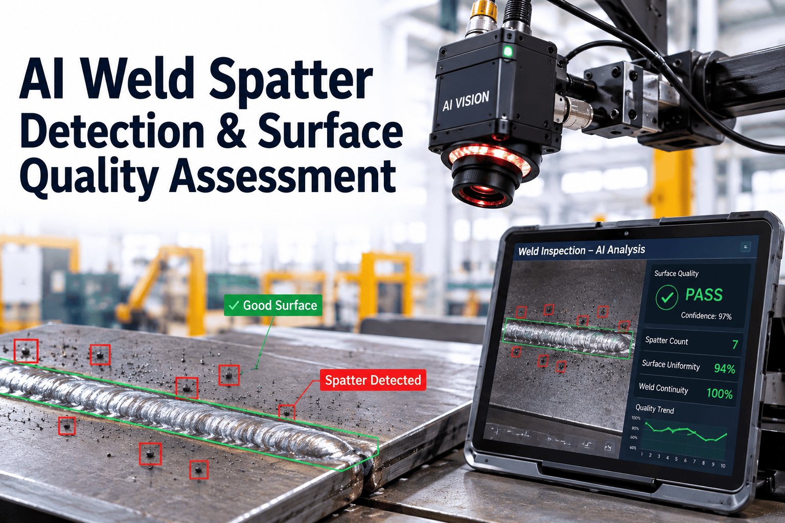
AI Weld Spatter Detection & Surface Quality Assessment
Spatter is easy to wave through as cosmetic and expensive to catch late. AI vision counts, classifies, and maps spatter density on every weld at the station where a two-second flag beats a five-minute grind.
Three Ways Spatter Becomes a Real Quality Problem
Spatter forms when molten metal is expelled from the weld pool during welding, from excessive current, incorrect polarity, or contaminated wire, and lands as scattered metallic droplets on the surrounding base metal. On a part that no one will ever see again after assembly, that's a minor issue. On a painted panel, an internal structural member, or a part headed to a corrosion-controlled environment, it is not. And because spatter formation is a byproduct of the same arc physics that determine weld penetration and bead shape, a welding process that's producing excessive spatter is very often drifting on other quality parameters at the same time — spatter is frequently the first visible symptom of a process problem that would otherwise go unnoticed until it produced a harder defect further down the line.
Spatter Isn't Uniform — Where It Lands Matters
A vision system doesn't just count spatter deposits, it maps where they land relative to the weld and the surrounding panel zones, because the same deposit count means something different depending on location. A cluster near the weld toe on a structural member is routine and expected. That same cluster on a Class A exterior surface eighty millimeters from the seam is a rework trigger.
This is the difference between a plant-wide spatter count and a usable inspection result: the same six deposits can be a non-event on a structural bracket and an automatic reject on an exterior panel, and the system needs to know which zone it's looking at to apply the right threshold rather than one flat spatter-count limit across the whole part. Building this zone map requires the vision system to know the part's geometry and surface classification in advance, typically configured against the CAD model or engineering drawing for each part number, so the correct threshold map loads automatically as different part variants move down the same line rather than requiring a manual reconfiguration between runs.
Flag Spatter at the Weld Station, Not at Paint Prep
iFactory's vision module counts, classifies, and zone-maps spatter on every weld in real time, routing genuine rework triggers to the operator before the part advances downstream.
Genuine Spatter vs. Cosmetic Surface Variation
Not every mark near a weld is spatter. Heat-affected-zone discoloration, minor surface oxidation, and normal reflectivity variation in the base metal can all resemble spatter to a simple brightness-threshold camera, and a system that can't tell the difference generates enough false rejects that operators start ignoring its alerts entirely. Reliable spatter detection separates the two by more than brightness alone, since a purely brightness-based check has no way to tell a shiny flat surface variation apart from a shiny raised metallic droplet, and treating both the same is exactly what erodes trust in the system over the first few production runs.
| Signal | Genuine Spatter | Cosmetic Variation |
|---|---|---|
| Surface Profile | Raised metallic droplet, proud of the surrounding surface | Flat — no measurable height change |
| Reflectivity | Sharp, localized reflectivity spike consistent with a metal bead | Gradual reflectivity shift across a wider area |
| Shape | Rounded, discrete deposits with defined edges | Diffuse boundary, no discrete edge |
| Location Pattern | Scattered discrete points radiating from the weld pool | Continuous band following the heat-affected zone contour |
iFactory's spatter model combines morphological classification with reflectivity contrast analysis rather than a single brightness threshold, so it distinguishes a genuine metallic deposit that requires grinding from a heat-tint mark that doesn't — the distinction that determines whether an operator's time gets spent on real rework or on chasing false alarms. This matters most in the first weeks after a new vision system goes live, since a system that over-flags cosmetic variation as spatter erodes operator trust quickly, and once operators start second-guessing or ignoring alerts, the plant is back to relying on manual judgment for the calls that matter, which defeats the purpose of automating the check in the first place.
Spatter Is a Symptom — The Cause Is Usually a Process Variable
Logging spatter counts against machine, shift, and consumable batch turns a per-weld cosmetic check into a process-diagnostic tool. When spatter density on one welding cell trends upward over a shift while every other cell stays flat, that pattern points quality engineering directly at the machine, the wire lot, or the gas supply feeding that specific station, instead of leaving them to guess from a pile of rejected parts with no shared cause visible. This is the same logic that applies to any process-driven defect, but spatter is unusually well suited to it because it's high-frequency and low-severity per instance — a single spatter deposit doesn't justify pulling a machine for maintenance, but a sustained upward trend across hundreds of welds is exactly the kind of pattern a logged, timestamped measurement history reveals well before it turns into a batch of rejected parts.
What Happens Between a Flagged Deposit and a Finished Part
Detecting spatter is only the first step. What actually determines whether a plant sees a return on the inspection system is what happens in the seconds after a deposit is flagged — whether that flag reaches the right person, at the right station, with enough context to act on it immediately, or whether it sits in a report someone reviews at the end of the shift.
The step most plants skip is the third one — detection without automatic routing just relocates the manual inspection bottleneck from the end of the line to a review screen, and an operator still has to notice the flag, decide what it means, and act on it. A system that routes the part automatically, based on the zone-specific threshold rather than a generic alert, is what actually removes the manual step instead of just moving where it happens. The fourth step is easy to treat as an afterthought, but it's the one that compounds in value over time: a single logged measurement is worth little on its own, but a full production run's worth of logged measurements against known machines and batches is what eventually lets a quality engineer answer questions no single inspection could — which stations run consistently clean, which consumable suppliers correlate with elevated spatter, and whether a recent maintenance action actually fixed the problem it was meant to fix.
Spatter Tolerance Isn't the Same Across Industries
How strictly spatter gets enforced depends heavily on what the part does and who sees it. A structural steel fabricator and an automotive body shop are welding under fundamentally different tolerance philosophies, even when the underlying spatter physics are identical.
| Industry | Primary Concern | Typical Tolerance |
|---|---|---|
| Automotive Body-in-White | Paint adhesion and appearance on Class A exterior panels | Near-zero on visible surfaces, moderate on structural |
| Structural Steel Fabrication | Corrosion protection and coating adhesion after blast/paint | Density-based, assessed per code and coating spec |
| Pressure Vessel & Piping | Surface preparation for subsequent NDT and coating integrity | Removal required before NDT on inspection surfaces |
| Heavy Equipment / Off-Highway | Functional interference and general appearance, lower cosmetic priority | Moderate — assessed mainly for fit-up and function |
Configuring a vision system's spatter thresholds to match the actual applicable standard for each part, rather than a single default sensitivity, is what keeps the system useful across a mixed production environment — a plant welding both automotive brackets and pressure vessel components on the same floor needs two different tolerance profiles running side by side, not one compromise setting that's too loose for one part and too strict for the other. Pressure vessel work adds a wrinkle the other three industries don't share as strongly: spatter left on the surface can interfere with subsequent non-destructive testing, since a raised metallic deposit near an ultrasonic or radiographic inspection point can produce a false indication or obscure a real one, which is why removal before NDT is frequently a hard procedural requirement rather than a cosmetic preference.
Spatter is the defect everyone underrates until they add up what it actually costs. On its own, one deposit is nothing — a grinder wheel handles it in seconds. But when a Class A body shop is finding spatter on ten percent of exterior panels after paint, that's ten percent of the line's throughput getting pulled for rework at the most expensive point in the process to fix it. The plants that get ahead of it aren't the ones with better grinders, they're the ones that started counting spatter at the weld station and noticed it was clustering on two robots with a wire feed issue nobody had flagged yet. Once you've seen that pattern play out a few times, you stop thinking of spatter counting as a cosmetic checkbox and start treating it as one of the cheapest early-warning signals available on the floor.
Frequently Asked Questions
See Spatter Detection on Your Own Weld and Surface Mix
iFactory's AI vision module counts, classifies, and zone-maps spatter on every weld at production speed, distinguishing genuine rework triggers from cosmetic surface variation.