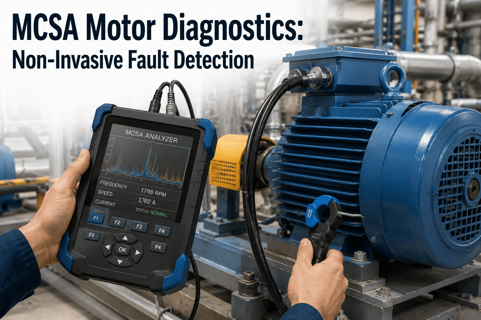
Every induction motor draws a current that carries far more information than the amps reading on a control panel meter suggests. Buried inside that waveform are frequency sidebands that shift the instant a rotor bar cracks, a bearing race pits, or an air gap goes eccentric — signals a technician would otherwise only find by shutting the motor down and opening the frame. Motor current signature analysis reads those sidebands from a current transformer clamped at the motor control center, while the motor keeps running and the process keeps producing. iFactory's predictive maintenance engineering team can help you map which motors in your population are the right starting point for a non-invasive current monitoring program.
Predictive Maintenance · Electrical Diagnostics
Motor Current Signature Analysis: Fault Detection Without Touching the Motor
MCSA detects broken rotor bars, air gap eccentricity, bearing defects, and stator winding faults by analyzing the current waveform at the motor control center — no accelerometer mounted on the housing, no confined-space entry, no shutdown required to get a reading.
What The Current Spectrum Reveals
8-10 wks
Typical rotor bar crack lead time before failure
3-6 mo
Bearing defect detection window ahead of seizure
Zero
Sensors mounted on the motor frame itself
40%+
Minimum load for a reliable fault signature
The Access Problem
Why "Non-Invasive" Matters More Than It Sounds
Vibration analysis, the traditional first line of defense for rotating equipment, requires a sensor physically mounted on the motor housing — usually at the bearing caps, sometimes at multiple points around the frame. Thermography requires a clear line of sight to the enclosure surface, and infrared imaging through a motor's own housing tells you almost nothing about what is happening electrically inside the winding or the rotor cage. Oil analysis is not even applicable to most induction motors, since the majority run on sealed or grease-lubricated bearings with no sample port to draw from.
Motor current signature analysis sidesteps every one of those access constraints. A clamp-on current transformer installed at the motor control center — often the same panel where protective relays and starters already live — is frequently the only hardware required. There is no need to approach the motor itself, no need to interrupt a guard or enclosure to reach a bearing cap, and no need to schedule a shutdown window just to get a baseline reading. For motors mounted in elevated locations, inside sealed enclosures, in classified hazardous areas, or buried behind other equipment where a technician cannot easily reach the frame, MCSA is often the only condition monitoring technique that is practically deployable at all.
The technique works because any mechanical or electrical fault disturbs the magnetic flux inside the machine, and that disturbance modulates the current the motor draws from the supply. A cracked rotor bar breaks the symmetry of the rotor circuit and introduces a reverse-rotating field component. A worn bearing introduces a periodic mechanical vibration that shows up as current sidebands at the bearing's characteristic defect frequencies. An eccentric air gap — static from a bent frame or dynamic from a bowed shaft — produces its own predictable harmonic pattern. None of these faults need to be seen or touched to be measured; they announce themselves electrically, and the current waveform is the messenger.
How Current Signature Analysis Works
From Raw Waveform to a Confirmed Fault Call
MCSA is not a single measurement — it is a signal processing pipeline that turns a raw current waveform into a specific, named fault condition with a severity trend behind it. The stages below are the sequence a production MCSA system runs on every capture cycle.
01
Current Capture at the Control Center
A clamp-on or split-core current transformer installed on the motor supply conductors samples the stator current at high resolution while the motor runs normally under load, with no interruption to the process.
↓
02
FFT Spectral Decomposition
A Fast Fourier Transform decomposes the time-domain current signal into its frequency components, producing the current spectrum with the supply frequency and its harmonics forming the reference baseline against which fault sidebands are measured.
↓
03
Slip and Pole-Pass Frequency Calculation
Using the motor's nameplate line frequency, pole count, and measured slip, the system calculates the exact frequencies where rotor bar sidebands are expected to appear — at line frequency times one plus or minus twice the slip — so it knows precisely where to look in the spectrum.
↓
04
Sideband Amplitude Measurement
The amplitude of each fault-frequency sideband is measured relative to the line frequency peak, expressed in decibels below the fundamental. A widely used rule of thumb treats rotor bar sidebands within roughly 35 decibels of the line peak as indicating a developing fault requiring attention.
↓
05
Baseline Trending Over Time
A single spectrum snapshot has limited diagnostic value on its own. The system compares each new reading against a stored healthy baseline for that specific motor, and trends sideband amplitude over weeks and months to distinguish a genuinely developing fault from normal load-driven variation.
↓
06
Fault Classification and Work Order Trigger
When a sideband pattern crosses its severity threshold, the system classifies the fault type — rotor bar, bearing, eccentricity, or stator — and publishes an alert with the trend history attached, so the maintenance team schedules the repair during a planned window instead of reacting to an unplanned trip.
See Fault Detection Run on Live Current Data
Watch a Current Spectrum Flag a Fault in Real Time
iFactory's diagnostics team walks through a live demo of sideband detection, baseline trending, and severity classification running against real motor current data from a production environment. Bring your motor population details and we'll map which units benefit most from continuous current monitoring.
Fault Coverage
What the Current Spectrum Can Diagnose
Each fault type produces a distinct signature in the current spectrum, at frequencies that can be calculated in advance from the motor's own nameplate data. The categories below cover the standard diagnostic scope of a current-based monitoring program.
Broken or Cracked Rotor Bars
Sidebands at line frequency × (1 ± 2s)
A fault mode that is genuinely difficult to catch by any other online technique, since rotor bars sit inside the rotating assembly where a vibration sensor mounted externally has no direct line to the source of the disturbance.
Air Gap Eccentricity
Static and dynamic sideband patterns
Static eccentricity typically points to a mounting or frame issue, while dynamic eccentricity suggests a bent shaft or advancing bearing wear — current analysis distinguishes between the two from the sideband pattern alone.
Bearing Defects
BPFO, BPFI, BSF, and FTF current modulation
Bearing degradation modulates the current at characteristic defect frequencies tied to race and cage geometry, giving a secondary detection path for motors where a vibration sensor cannot be mounted close enough to the bearing housing.
Stator Winding Faults
Negative-sequence current components
Inter-turn shorts and winding insulation degradation show up as negative-sequence current components that are effectively invisible in the raw time-domain waveform but stand out clearly once the spectrum is decomposed.
Misalignment and Load Anomalies
Periodic load-driven current variation
Angular and parallel shaft misalignment create periodic load variations that modulate stator current in a recognizable pattern, giving a useful cross-check when combined with vibration data from the driven equipment.
Stator Slot and Supply Anomalies
Slot-passing frequency sidebands
Sidebands around the stator slot-passing frequency — the number of stator slots multiplied by running speed — flag stator winding and supply-side issues that would otherwise only surface as unexplained heating or nuisance trips.
Method Comparison
Where MCSA Fits Against Other Condition Monitoring Techniques
MCSA does not replace every predictive technique in a motor reliability program — it is strongest when combined with vibration analysis for full mechanical and electrical coverage. The comparison below reflects where each method's access requirements and fault coverage actually sit.
| Method |
Physical Access Required |
Rotor Bar Faults |
Bearing Faults |
| Vibration Analysis |
Sensor mounted on housing/bearing cap |
Difficult — indirect detection only |
Strong — direct, established method |
| Infrared Thermography |
Line of sight to enclosure surface |
Not detectable |
Late-stage only, after heat generation |
| Oil Analysis |
Sample port on lubrication system |
Not applicable |
Applicable only to oil-lubricated bearings |
| Ultrasonic Testing |
Sensor near bearing housing |
Not detectable |
Strong — early-stage friction and impacting |
| Motor Current Signature Analysis |
Current clamp at motor control center |
Strong — a fault mode few other methods catch online |
Moderate — useful secondary path |
The pattern that matters for a reliability program: MCSA is the only technique on this list that requires no access to the motor itself, which is precisely why it is the practical choice for elevated, enclosed, or hazardous-area motors that other methods cannot reach.
Turnkey Deployment
Continuous Current Monitoring Live in 6–10 Weeks
iFactory ships current signature monitoring as a pre-configured bundle — current transformers sized to your motor population, an edge processing unit pre-loaded with sideband detection models, and integration to your existing CMMS and historian defined as part of the deployment scope rather than a separate discovery phase.
Weeks 1–3
Motor Population Survey
Nameplate data, pole count, and control center access surveyed for each motor in scope, with priority given to motors that are hardest to reach for vibration sensor mounting or are in classified hazardous areas.
Weeks 4–7
Baseline Capture and Calibration
Current transformers installed at the motor control center and healthy baseline spectra captured across a range of load conditions, with slip and pole-pass frequencies calculated and stored for each motor.
Weeks 8–10
Go-Live and Trend Monitoring
Continuous monitoring goes live against the stored baselines, with alert thresholds tuned per fault type and 24×7 remote review by the iFactory reliability team for developing sideband patterns.
1000+Clients on iFactory platform
99.9%Platform uptime SLA
24×7Remote reliability monitoring
6–10wkLive deployment timeline
What Reliability Teams Actually Gain
The Operational Impact of Reading the Current Instead of Opening the Motor
The case for current signature monitoring is not just early fault detection — it is the number of unplanned motor trips, confined-space entries, and reactive teardowns that disappear once a motor's electrical health is visible continuously from the control center.
Fault Detection Without Confined-Space Entry
Motors mounted in elevated, enclosed, or classified hazardous locations get continuous electrical health visibility without a technician ever approaching the frame to mount a sensor.
Weeks of Lead Time Before Failure
Rotor bar and bearing faults trended against a healthy baseline typically surface months before a catastrophic failure would otherwise halt production without warning.
A Fault Class Other Methods Miss
Rotor bar cracks are difficult to detect with vibration analysis alone, giving reliability teams electrical fault coverage that closes a genuine blind spot in the monitoring program.
Lower Cost Per Monitored Motor
A single current transformer at the control center can cover a motor that would otherwise require multiple vibration sensors, cabling, and mounting hardware distributed across the frame.
Common Questions
Frequently Asked Questions
Does MCSA require the motor to be shut down for a reading?
No — the entire premise of the technique is that it works while the motor runs under normal load, which is what makes it non-invasive in the first place. The current transformer is typically clamped at the motor control center, a location that is almost always accessible without opening the motor enclosure or interrupting the process it drives. Accurate fault signatures do require the motor to be operating at a reasonable load, generally above roughly forty percent, since low-load conditions weaken the sideband amplitude and reduce detection reliability. For motors that run intermittently or at very light load,
iFactory's engineering team can help determine whether current analysis or an alternative technique is the better fit.
Can MCSA replace vibration analysis entirely?
Not entirely, and the strongest reliability programs treat the two as complementary rather than interchangeable. Vibration analysis remains the more established and direct method for many bearing and mechanical faults where a sensor can be mounted close to the source, while current analysis brings unique strength in detecting rotor bar and stator electrical faults that vibration struggles to isolate. The combination gives full mechanical and electrical coverage, and for motors where a vibration sensor genuinely cannot be mounted, current analysis becomes the primary rather than the secondary method. Booking a demo is the fastest way to see how the two techniques would divide coverage across your specific motor population.
How early does MCSA typically catch a developing fault?
Detection lead time varies by fault type, but rotor bar cracks trended against a healthy baseline are commonly identified roughly eight to ten weeks before the fracture propagates far enough to threaten adjacent bars and cause full rotor failure. Bearing defects picked up through current-induced modulation typically surface three to six months ahead of a catastrophic seizure, giving maintenance planners a genuine window to schedule a repair during a planned outage instead of responding to an unplanned trip. These windows depend on trending consistently from a known baseline rather than a single spectrum snapshot, which is why continuous monitoring produces materially better outcomes than periodic spot checks.
What hardware does a current signature monitoring installation actually require?
In most installations, a clamp-on or split-core current transformer installed on the motor supply conductors at the motor control center is the only hardware that touches the electrical system, paired with a data acquisition and spectrum analysis unit that can sit in the same panel or nearby cabinet. There is no sensor mounted on the motor frame, no cabling run out to the machine itself, and no modification to the motor or its enclosure. This is a large part of why current analysis is often the only practically deployable option for motors in classified hazardous areas, elevated platforms, or locations where a technician cannot safely or easily reach the machine to mount conventional sensors.
How does this connect to our existing SCADA or CMMS system?
The current monitoring platform publishes classified fault alerts and severity trends — not raw current data — through standard integration paths that feed directly into existing SCADA dashboards and CMMS work order systems. From the maintenance planner's side, a detected rotor bar fault or bearing defect looks like any other work order trigger, complete with the trend history that justifies scheduling the repair during the next planned outage rather than reacting to a trip. The turnkey deployment scope defines this integration engineering as a defined phase upfront, and
booking a demo is the fastest way to see how the alert and trend view would look against your specific CMMS.
Stop Waiting for the Motor to Tell You It Failed
Turnkey Current Signature Monitoring, Live in 6–10 Weeks
iFactory's motor current signature analysis platform ships as a pre-configured bundle — current transformers sized to your motor population, sideband detection models pre-loaded, and CMMS integration scope defined upfront. Get a turnkey quote for the full deployment, or start with a pilot on your hardest-to-reach or most critical motors to prove the fault detection before scaling across the plant.