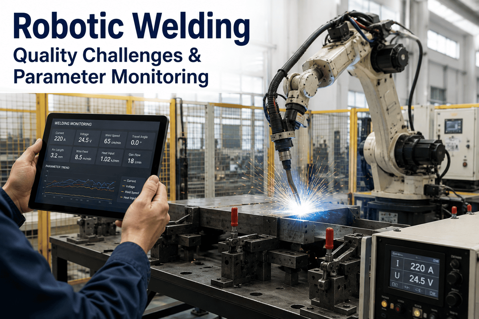
Robotic Welding Quality Challenges & Parameter Monitoring

By Johnson on August 12, 2026

robotic-welding-quality-challenges-parameter-monitoring

A robotic weld cell will repeat the exact same path a thousand times without complaint, which is precisely why a small drift in torch angle, wire feed, or joint fit-up can produce a thousand nearly identical defects before anyone notices. Automation removed the inconsistency that comes from a tired welder at the end of a shift, but it introduced a different failure mode entirely: a robot has no sense that something is wrong, so it will keep laying down a flawed weld with the same confidence as a perfect one. Parameter monitoring is what gives a robotic cell the judgment it does not have on its own. Learn how iFactory adds that layer at ifactory support.

iFactory Robotic Weld Quality

Robots Don't Get Tired. They Just Repeat the Same Mistake Faster.

Arc monitoring, seam tracking, and real-time parameter verification catch the drift that a robot's own controller has no way to detect — before a shift's worth of parts needs to be reworked or scrapped.
Repeatable
Failure at the same rate as success
Silent Drift
No alarm until a defect is found downstream
Millisecond
Window where arc data actually shows a problem

Automation Solved One Quality Problem and Created Another

Manual welding quality problems are usually attributed to human variability — fatigue, inconsistent technique, or a rushed pass near the end of a shift — and robotic welding was adopted in large part to remove that variability from the process. It works, in the sense that a robot will hold the same path, speed, and nominal parameters weld after weld with a consistency no human hand can match. What robotic welding does not solve on its own is drift: a liner wearing down in the wire feed system, a contact tip degrading, a fixture shifting slightly out of tolerance, or a joint fit-up that was slightly off on the incoming part. None of these register as an error to a standard robot controller, because the robot is executing its programmed path correctly — it simply has no way to know that the physical result of executing that path has quietly changed.

The consequence is that robotic cells can produce a run of visually similar but structurally inconsistent welds without triggering a single fault code, and the first sign of a problem is often a failed destructive test, a customer rejection, or an NDE finding on a part that was welded days or weeks earlier. By the time that feedback loop closes, the drift has usually affected far more parts than a manual process with the same underlying issue would have, because nothing on the floor slowed down or looked different in the meantime.

This is the specific irony of robotic weld quality: the same consistency that makes automation attractive is what makes an undetected defect so costly. A manual welder having a bad day tends to produce visibly inconsistent welds that a trained eye catches quickly, because human error rarely repeats identically pass after pass. A robot executing a flawed program or working through a degraded consumable produces the opposite pattern — every weld looks the same, and every weld carries the same underlying issue, which means a sampling-based inspection plan built around catching scattered individual defects is structurally mismatched to what robotic drift actually produces.

Wire Feed Drift
Liner wear or contact tip degradation gradually changes deposition rate without tripping a fault on the robot controller.
Fixture Shift
A clamp or locator that has worked loose changes joint position slightly, enough to affect penetration but not enough to stop the cycle.
Incoming Fit-Up
Parts arriving from upstream operations slightly out of tolerance change the actual joint gap the robot is welding into.
Consumable Wear
Nozzles and tips degrading over a production run gradually change gas coverage and arc stability without an obvious visual cue.

Four Layers of Monitoring That Catch What the Controller Misses

A robot controller confirms that it executed its programmed motion. It does not confirm that the weld it produced actually meets the quality standard, because those are two different questions answered by two different data sources. Parameter monitoring adds a second, independent layer of verification that watches the actual physical result of the weld — arc behavior, seam position, and process parameters — rather than just confirming the robot followed its path. The four monitoring layers below work together, each catching a different category of drift that the others would miss on their own, and a mature deployment typically runs all four simultaneously rather than treating any single layer as sufficient coverage by itself.

01
Arc Monitoring
Voltage, current, and arc stability are sampled continuously through the weld, catching short-duration instability events like spatter bursts, arc outages, or irregular droplet transfer that a post-weld visual inspection would never catch after the fact.
02
Seam Tracking Verification
Laser or through-arc sensing confirms the torch is actually following the real joint position, not just the taught path, and corrects in real time when incoming part variation has shifted the seam from where the program expects it to be.
03
Parameter Verification
Travel speed, wire feed speed, and gas flow are checked against the qualified procedure for that joint on every single weld, flagging any pass that drifted outside the approved window even if the robot completed its motion without error.
04
Automatic Correction
Where the process allows it, minor deviations are corrected within the weld itself, adjusting torch position or parameters on the fly rather than simply logging a deviation for someone to review after the part has already left the cell.

Where the Data Actually Comes From

Parameter monitoring is only as good as the sensing layer feeding it, and different defect classes require different data sources to catch reliably. Voltage and current sampling from the power source catches arc instability and short-duration transfer problems, but it says nothing about whether the torch was actually positioned over the joint correctly. Seam tracking sensors, whether laser-based or through-arc, close that gap by confirming physical position against the real joint rather than the taught path alone. Neither source on its own is a complete picture — a weld can have perfect arc stability while tracking a joint that has drifted out of position, and it can be perfectly positioned while the arc itself is unstable from a worn liner. This is why a monitoring system built around a single data source tends to have blind spots that only show up once a specific failure mode happens to occur in production.

The practical implication for a plant evaluating monitoring options is that the sensing hardware matters as much as the software analyzing it. A system that only reads power source data can be added quickly and cheaply, but it will miss fit-up and fixture-related defects entirely. A full deployment that adds seam tracking sensing alongside arc monitoring costs more up front and takes longer to commission, but it closes the gap on the defect classes that arc data alone cannot see, which is usually the majority of drift-related issues on a fixtured robotic cell.

The Monitoring Loop Running Alongside Every Weld
ARC + SEAM SENSORS LIVE PARAMETER COMPARISON WITHIN TOLERANCE WELD LOGGED DEVIATION DETECTED CORRECT OR HOLD FOR REVIEW Every weld pass is checked in this loop before it is logged as complete
See This on Your Own Weld Data

Run Our Monitoring Model Against a Sample Weld Log

Share a batch of parameter data from one of your robotic cells and we will show you what drift, if any, is already hiding inside a run you thought was clean.

Manual Inspection vs. Continuous Parameter Monitoring

Most robotic cells still rely on a manual inspection step somewhere downstream — a visual check, a sample-based NDE plan, or a periodic destructive test pulled from the run. That approach was designed around manual welding, where defect patterns tend to be scattered and individual. Robotic welding produces a different defect signature: consistent, repeated, and often invisible to a visual check until the underlying cause is found. The comparison below shows why a sampling-based inspection plan built for manual welding tends to under-catch the specific failure modes that robotic drift actually produces.

Factor Sample-Based Manual Inspection Continuous Parameter Monitoring
Coverage A percentage of welds, chosen by sampling plan Every single weld pass, without exception
Detection speed for drift Delayed until the next sample happens to be checked Immediate, within the weld pass where it occurred
Root cause visibility Limited to what a visual or destructive check reveals Full parameter history tied to the specific deviation
Rework scope when found Entire lot since the last known-good sample Narrowed to the specific parts affected by the deviation
Best suited for Low-volume, high-variability manual processes High-volume, repeatable robotic weld cells

What Happens Between a Deviation and a Corrected Weld

Catching a deviation is only useful if something happens next fast enough to matter. The sequence below is what runs between the moment arc or parameter data crosses a tolerance threshold and the part either getting corrected in-process or flagged before it moves to the next station, all within the same weld cycle rather than discovered on a report the next morning.

From Deviation to Resolution, in the Same Cycle
1
Sense
Arc sensors and seam tracking sensors sample the weld continuously throughout the pass, not at fixed checkpoints.
2
Compare
Live readings are checked against the qualified welding procedure specification for that joint in real time.
3
Correct or Flag
Minor deviations trigger an in-process correction where the process allows it; larger ones hold the part for review.
4
Log
The full parameter trace is stored against the part serial number, searchable for traceability and audit purposes later.
5
Trend
Repeated deviations across multiple parts are pattern-matched to flag a likely root cause, such as consumable wear.

Not sure whether your current cell already has this data available or needs added sensing? Ask our team to review your current setup before you invest in anything new.

What Plants Measure After Adding Parameter Monitoring

The value of parameter monitoring shows up in numbers a weld shop is already tracking on a quality scorecard — scrap rate, rework hours, and NDE reject rate — rather than a new metric invented for the technology. The ranges below reflect what mid-size manufacturers running robotic weld cells have reported after a year of continuous monitoring, with the actual result depending heavily on baseline drift frequency and how tightly the correction logic is tuned to each joint type.

35-55%
Reduction in weld-related scrap and rework
Same-Cycle
Deviation detection instead of next-day discovery
Per-Part
Traceable parameter record for every weld pass
60-70%
Fewer parts pulled for destructive sample testing

How a Monitoring Deployment Actually Rolls Out on a Weld Cell

Adding parameter monitoring to a robotic weld cell is not a single sensor install — it is a calibration process that has to prove itself against known-good and known-bad welds before the floor trusts an automated hold or correction decision. The four phases below reflect how most weld shops sequence a deployment, moving from a single joint type to broader coverage only once the thresholds have been validated against real production data.

Phase 1
Assess the Cell
Review the existing power source, robot controller, and fixturing to determine what data is already available and what sensing needs to be added for full coverage.
Phase 2
Install and Baseline
Add any required sensors and collect a baseline of known-good welds across the target joint types to establish what normal process variation actually looks like.
Phase 3
Calibrate Thresholds
Set deviation thresholds against the qualified welding procedure specification for each joint, validating against both known-good and known-bad samples before going live.
Phase 4
Expand Coverage
Widen monitoring to additional joint types and cells in stages, reviewing false alarm and catch rates monthly to tighten thresholds as confidence grows.

Frequently Asked Questions

Does parameter monitoring require replacing our existing robotic welders?
No, monitoring is typically added onto existing robotic cells rather than requiring a hardware replacement, using sensors and data taps that integrate with the current welding power source and robot controller. Most industrial welding power sources already generate the raw voltage and current data needed; the monitoring layer captures, compares, and acts on that data in real time rather than requiring a completely new welding platform. The scope of what needs to be added depends on your current cell's age and instrumentation, which is confirmed during an initial assessment. Talk to our team about what your specific cells would need.
How does the system tell the difference between a false alarm and a real quality issue?
Thresholds are set against the qualified welding procedure specification for each specific joint type, not a single generic tolerance band applied across every weld in the cell, which is what keeps the alert rate meaningful rather than constant background noise the floor learns to ignore. During commissioning, historical weld data and known-good sample welds are used to calibrate what normal variation actually looks like for that joint before the monitoring goes live in production. Deviations that fall within expected process noise are logged but not flagged, while genuine threshold crossings trigger the correction or hold logic. Book a walkthrough to see how thresholds are set for a joint type similar to yours.
Can this integrate with our existing quality management and traceability systems?
Yes, integration with existing QMS and traceability platforms is a standard part of deployment, with per-weld parameter data flowing into the same system your quality team already uses to manage nonconformances and certifications. That means a flagged deviation creates a record tied to the part serial number automatically, rather than requiring a quality engineer to manually cross-reference a separate monitoring report against production records after the fact. Standard integrations are available for common manufacturing quality platforms, and site-specific connections are handled during setup. Reach out to our integration team for a walkthrough of specific systems we work with today.
What kinds of defects does parameter monitoring actually catch that visual inspection misses?
Parameter monitoring is particularly strong at catching subsurface and process-related issues that never show up as a visible surface defect — incomplete fusion from a subtle arc instability, porosity risk from a gas flow deviation, or inconsistent penetration from a wire feed drift, all of which can look identical to a good weld on the surface while failing well below spec structurally. Visual inspection remains valuable for surface-level defects like spatter, undercut, and visible porosity, which is why the two methods are typically run together rather than one replacing the other entirely. Contact our support team to see example defect classes our monitoring models are trained to catch.
How long does a typical parameter monitoring deployment take on one weld cell?
A single-cell pilot, from initial assessment through sensor installation and threshold calibration, typically runs six to ten weeks depending on how many joint types and welding procedures need to be qualified against historical data before going live. Plants with clean, well-documented welding procedure specifications and existing digital weld data move faster than those still relying on paper travelers, since much of the calibration work depends on having good reference data to compare against. Book a scoping call to get a realistic timeline for your specific cell configuration.
Catch the Drift Before It Ships.

See What Your Own Weld Data Is Already Telling You

Send us a sample of parameter data from one of your robotic weld cells. We will show you what our monitoring models flag, and what it would take to catch it in real time going forward.

Share This Story, Choose Your Platform!