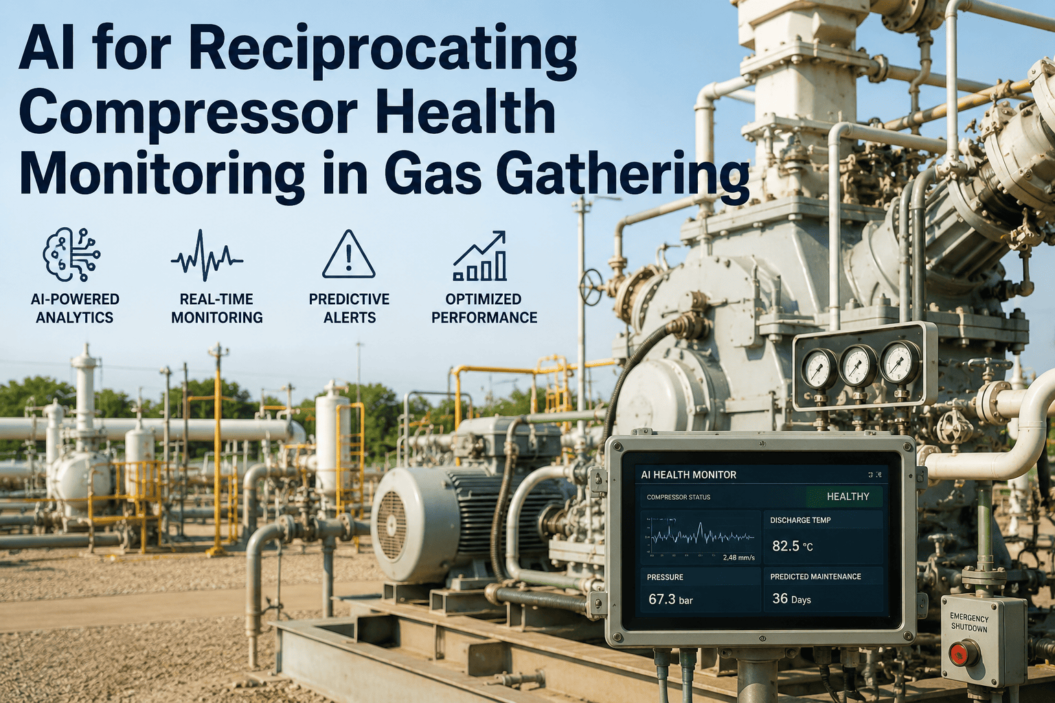
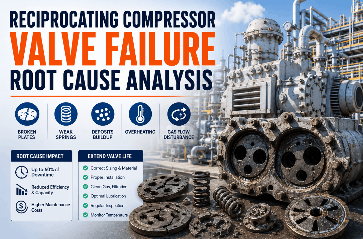
Reciprocating compressors run gas gathering operations, and they also fail more often than any other major rotating asset on the field. Every stroke loads and unloads the rod, valves slam open and closed at line frequency multiples, rider bands wear against the cylinder wall, and packing wears against the rod, all while a single unplanned shutdown can shut in wellhead production for days. Suction and discharge valves alone account for the highest failure rate of any component on the machine, cycling millions of times a week until a cracked plate or a fatigued spring turns a routine cycle into an unplanned trip. iFactory fuses vibration, crank angle, in-cylinder pressure, rod drop, and valve cap temperature data into a continuous health model built specifically for reciprocating compressors, flagging valve leakage, rider band wear, and packing degradation weeks before they force a shutdown. You can book a demo to see your own compressor's failure signatures modeled against real operating data.
AI PREDICTIVE MAINTENANCE · RECIPROCATING COMPRESSORS · GAS GATHERING
The Machine With the Most Wear Parts Gets the Least Warning Before It Fails
Reciprocating compressors generate more vibration energy at more frequencies than any other rotating asset in the field, yet most gas gathering sites still rely on daily walk-by checks and scheduled oil sampling to catch failures that develop between visits. iFactory watches every stroke continuously.
#1
Failure-rate component: suction and discharge valves
$180-340K
Typical cost per day of an unplanned compressor station shutdown
30%
Rod drop increase above baseline that signals rider band or ring wear
up to 36%
Reduction in unplanned downtime achievable with data-driven predictive maintenance
WHY THIS MACHINE FAILS DIFFERENTLY
Four Wear Paths That Develop Long Before a Shutdown Trip
Unlike a centrifugal machine spinning smoothly at a fixed speed, a reciprocating compressor compresses gas in discrete strokes, thousands of times an hour, concentrating wear into components that must be tracked individually, cylinder by cylinder. Each of the four wear paths below develops gradually and leaves a measurable signature well before it becomes an unplanned trip, provided something is actually watching for it between scheduled inspection rounds. This is also why a maintenance program built around a fixed calendar interval, rather than actual condition, tends to either replace parts too early and waste good service life, or wait too long and let a developing fault reach the point of unplanned failure, since the same wear path can progress at very different rates depending on gas composition, load profile, and how abrasive the incoming stream happens to be on a given well.
Valve Leakage
A cracked plate or fatigued spring lets gas flow back across a valve that should be sealed, cutting delivered capacity and driving cylinder temperature upward as reverse flow warms the gas locally.
Rider Band Wear
Rider bands carry the piston's weight without metal-to-metal contact, and once they wear past their operational limit the piston begins scoring the cylinder liner, an expensive repair to reverse.
Packing Degradation
Stacked rings sealing the rod against atmosphere wear gradually under spring load, and a step change in leak rate or case temperature signals ring wear or rod damage underway.
Crosshead & Bearing Wear
The crosshead and connecting rod bearings absorb reversing loads on every stroke, and developing wrist pin or bushing wear shows up in vibration signatures long before rod failure.
THE SENSING LAYER THIS MACHINE ACTUALLY NEEDS
What Has to Be Measured to See These Failures Coming
Reciprocating compressors already have API-standard mounting locations for condition monitoring instrumentation built in, though many units in the field, particularly older ones, remain uninstrumented today. The signals below are what turns a reactive maintenance program into a predictive one, and most of them can be added without touching the compressor's control logic. No single signal tells the whole story on its own, which is exactly why a model that fuses several of them together catches faults that a single-sensor threshold would miss entirely, since a genuine developing fault typically shows up as a consistent pattern across two or three of these signals at once rather than a spike in just one.
01
Crank Angle & In-Cylinder Pressure
Pressure-volume analysis synchronized to crank position is the single most effective diagnostic for valve condition, revealing a characteristic re-expansion loop when a suction valve leaks.
02
Rod Drop Position
Continuous measurement of piston rod position relative to the cylinder bore detects rider band and ring wear as it develops, well before a scheduled monthly check would catch it.
03
Valve Cap Temperature
A rise of 10 to 15 degrees over baseline discharge temperature is a strong early indicator of a leaking valve or a worn piston ring before frame vibration responds.
04
Crosshead & Frame Vibration
High-frequency vibration at the crosshead surfaces wrist pin and bushing wear, while frame-level vibration trends flag bearing and structural issues developing across the whole machine.
05
Packing Vent Flow & Oil Analysis
Vent flow monitoring tracks escalating packing leakage against OEM specification, while spectrometric oil analysis and particle counting catch abrasive wear before vibration amplitudes shift.
FROM RAW SIGNAL TO WORK ORDER
The Five-Stage Path From Sensor Data to a Scheduled Repair
Turning continuous compressor data into a trustworthy maintenance recommendation is a defined analytical sequence, not a single alarm threshold. Each stage below has to hold up reliably across changing load, ambient temperature, and gas composition for the resulting alerts to be worth acting on.
1
Continuous Multi-Signal Capture
Vibration, dynamic pressure, temperature, rod position, and process data stream continuously from the compressor and its auxiliary systems into a unified time-series dataset.
2
Per-Cylinder Baseline Modeling
Because wear develops independently in each cylinder, the model establishes a normal operating baseline for every cylinder and valve individually rather than treating the machine as one unit.
3
Failure Mode Classification
Deviations are matched against known signatures for valve leakage, rider band wear, packing degradation, and bearing wear, distinguishing which specific fault is developing.
4
Remaining Useful Life Estimate
Where trend data supports it, the model forecasts a remaining useful life window, giving maintenance planners a target date rather than a vague future warning.
5
Prioritized Work Order Dispatch
A specific, cylinder-level finding with confidence and urgency is routed to the maintenance team, so the repair is scheduled during a planned outage instead of forcing an emergency trip.
REACTIVE VS PREDICTIVE ON THE SAME MACHINE
What Actually Changes When Monitoring Runs Continuously
The comparison below reflects the same reciprocating compressor under two different maintenance philosophies. The difference is not a marginal improvement in scheduling, it is the gap between finding out a valve failed and finding out a valve is about to fail. The pattern holds across nearly every wear path on this machine: the underlying physics of how a valve leaks or a rider band wears does not change between the two columns, only how early the signature is caught and how much runway the maintenance team has to act on it before the fault becomes a forced outage.
| Maintenance Factor |
Reactive / Manual Rounds |
iFactory Predictive Model |
| Valve leak detection method |
Portable temperature checks, often less than daily |
Continuous PV analysis synced to crank angle |
| Rider band wear tracking |
Manual rod drop measurement, monthly at best |
Continuous rod position monitoring against baseline |
| Packing leak escalation |
Noticed during a scheduled walk-by, if at all |
Vent flow trended continuously against OEM spec |
| Repair timing |
Emergency trip or run-to-failure |
Scheduled during a planned outage window |
| Cylinder-level visibility |
Whole-machine symptoms, hard to isolate the cylinder |
Independent baseline and diagnosis per cylinder |
WHAT SITS ON THE OTHER SIDE OF A MISSED SIGNAL
The Economics Behind an Unplanned Gas Gathering Shutdown
A compressor failure in a gas gathering system rarely stays contained to the compressor itself. Depending on the gathering agreement and pipeline contract in place, every hour of downtime has a direct, calculable dollar value, and the wells feeding that compressor may need to shut in until the unit is repaired and restarted. The indirect costs compound the direct ones: emergency parts sourcing, overtime labor, and contractor mobilization to a remote wellhead site all run at a premium compared to a repair scheduled weeks in advance during a planned outage window, which is precisely the difference a predictive finding is designed to create.
$180-340K
Typical cost per day of an unplanned compressor station shutdown in oil and gas operations
67%
Share of critical failures that occur as "unexpected" despite sensor data showing degradation weeks earlier
27 days
Average annual unplanned downtime reported across offshore oil and gas operations
Put a Number on What Unplanned Downtime Is Costing Your Wells
iFactory can estimate the production and downtime cost tied to your compressor fleet's current failure history before you commit to a pilot.
GETTING TO A LIVE PREDICTIVE MODEL
From Historian Data to Cylinder-Level Diagnosis in 12 Weeks
A predictive maintenance rollout for reciprocating compressors does not require a plant-wide sensor overhaul before the first insight lands. The path below starts with whatever instrumentation and historian data already exists and builds toward full cylinder-level diagnosis, station by station across a fleet if that is how the field is organized, rather than requiring every site to be ready before any of them go live.
WEEKS 1-4
Historian Connection & Sensor Gap Assessment
Connect existing process historian data, assess current sensor coverage against API monitoring points, and identify any gaps worth closing for full diagnostic coverage.
WEEKS 5-8
Per-Cylinder Baseline Training
Train baseline models for each cylinder and valve using historical data, validating against known past failures to confirm diagnostic accuracy before going live.
WEEKS 9-12
Live Monitoring & Maintenance Handoff
Alerts and remaining-useful-life forecasts go live to the maintenance team, integrated with the existing work order system so findings become scheduled repairs.
FREQUENTLY ASKED QUESTIONS
What Gas Gathering Operators Ask Before Deploying
Do we need to install new sensors, or can this work with the instrumentation already on our compressors?
Most reciprocating compressors already have API-standard mounting locations for condition monitoring instrumentation built into the design, even when that instrumentation was never actually installed, which means adding sensors is often a matter of populating existing mounting points rather than a full redesign. Older units in the field are more likely to be missing key sensors such as rod drop or crank angle instrumentation, and a gap assessment during the first phase identifies exactly what would need to be added for full diagnostic coverage. Many sites can begin with whatever process historian data already exists and add targeted sensors only where the assessment shows a genuine gap. You can
book a demo to review your current instrumentation against what full coverage would require.
Will this integrate with the compressor's existing control system, or does it require changes to control logic?
Predictive monitoring is deployed as a parallel data layer that reads sensor and process signals without requiring any changes to compressor control logic or safety and anti-surge systems, since the goal is to add diagnostic visibility rather than to alter how the machine actually runs. This separation is deliberate, since control logic changes on safety-critical equipment carry their own approval and validation requirements that a monitoring deployment should never need to touch. Our team can
review your specific control system architecture to confirm the integration approach before a pilot begins.
How does the system tell the difference between normal load variation and an actual developing fault?
Because a reciprocating compressor's operating signature shifts naturally with suction pressure, discharge pressure, and load step changes that are a normal part of gas gathering operation, the model establishes a per-cylinder baseline that accounts for these operating conditions rather than comparing raw values against a single fixed threshold. A genuine developing fault, such as valve leakage or rider band wear, produces a signature that persists and trends in a specific direction across changing load conditions, which is what separates it from routine operational variation. This baseline approach is validated against your own historical data and known past failures before the system is trusted to flag live events. You can
book a demo to see this validation on a comparable compressor's operating history.
Can this cover a fleet of compressors spread across multiple remote wellhead sites?
Yes, and this is one of the more common deployment patterns in gas gathering, where a fleet of reciprocating compressors distributed across a large geographic area each needs individual monitoring rather than a single point solution at one station. Remote sites with limited connectivity are supported through edge-level data capture that stores and forwards readings, so continuous monitoring does not depend on constant high-bandwidth connectivity at every wellhead. Fleet-wide findings are aggregated into a single dashboard so a maintenance planner covering many sites can prioritize across the whole fleet rather than site by site. Our support team can
walk through your specific site layout and connectivity to confirm the right deployment pattern.
How soon after going live would we expect to see an actual finding that prevents a failure?
Because many gas gathering compressors already carry developing wear, such as a valve trending toward leakage or a rider band approaching its wear limit, the initial baseline training phase frequently surfaces a genuine finding before the system is even fully live, simply by applying the diagnostic models to historical and current data. Once live, the specific timeline for the first prevented failure depends on your fleet's age, service severity, and current maintenance discipline, though sites moving from manual rounds to continuous monitoring typically see their first meaningful finding within the initial weeks of live operation. You can
book a demo to review the typical finding timeline against your specific fleet profile.
Stop Finding Out About a Failing Valve After It Fails
Every valve leak, worn rider band, and degrading packing case leaves a signature in the data weeks before it becomes an unplanned trip. iFactory watches for it continuously so your team gets a work order instead of an emergency call.