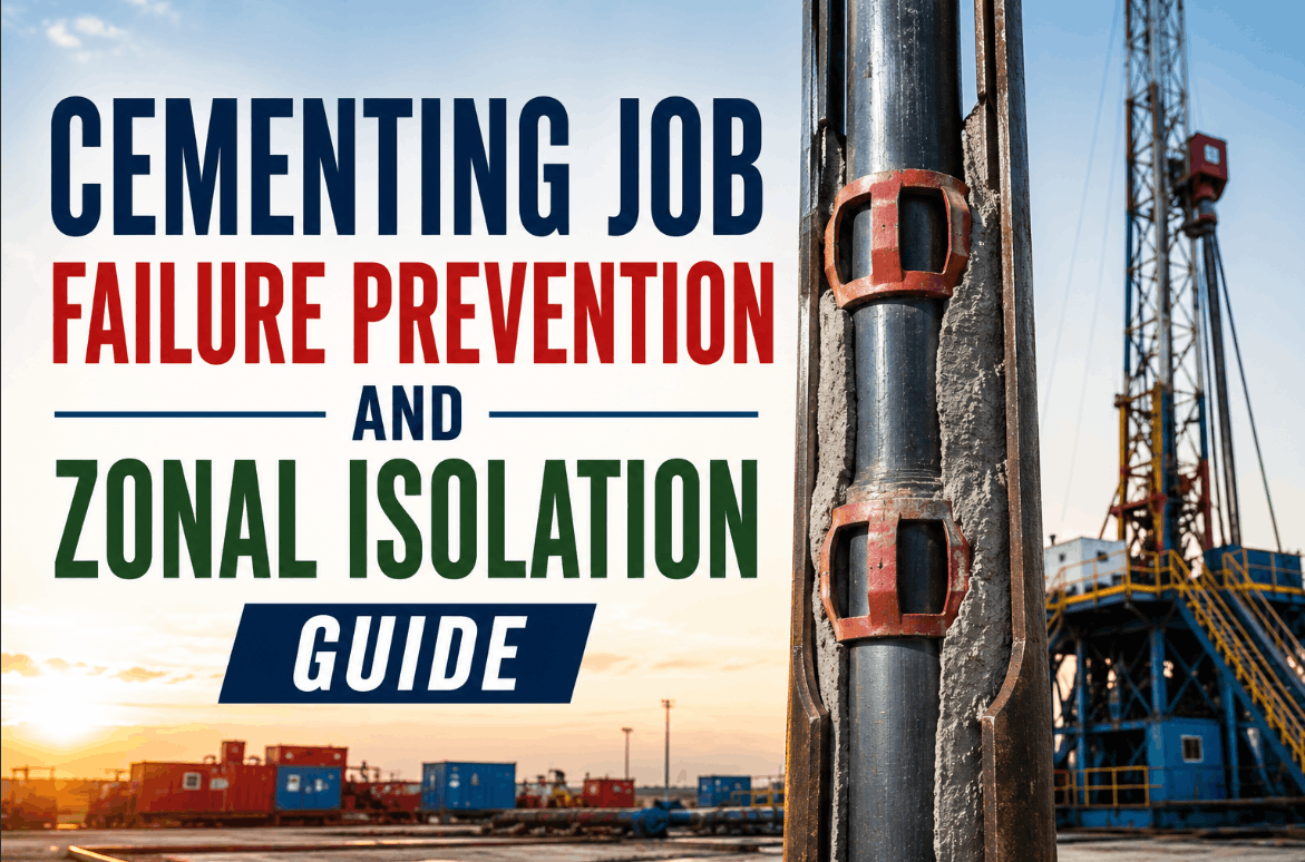
Cementing Job Failure Prevention and Zonal Isolation Guide
By Henry Green on June 16, 2026
Every well construction team knows that a failed primary cementing job is not a drilling problem — it is a well-life problem. When cement does not isolate zones as designed, sustained casing pressure appears at the surface within weeks or months, remedial squeeze operations are triggered at costs ranging from $250,000 to $2 million per intervention, and the well's production profile is compromised for its entire producing life. That reality is the documented consequence of spacer contamination, inadequate centralization, or slurry design that does not account for downhole conditions at the time of placement. Unlike a casing failure detected immediately during pressure testing, a compromised cement bond can remain hidden until it becomes visible as annular pressure buildup — at which point the only remedy is an intervention the well was never designed to accommodate. The engineering question is not whether to invest in better cementing design — it is which design parameters, placement techniques, and evaluation methods produce the reliable zonal isolation that well economics and regulatory compliance demand.
Evaluate Your Cementing Design Workflow Against Industry Best Practices
iFactory's digital well construction platform integrates pre-job modeling, real-time execution monitoring, and post-job evaluation into a single engineering workflow purpose-built for zonal isolation assurance. See how leading well construction teams are reducing cementing failures through integrated digital engineering.
The True Cost of Cementing Job Failures in Well Construction
The economic impact of a cementing failure extends far beyond the cost of the remedial cement job itself. When zonal isolation is lost, operators face sustained casing pressure that requires ongoing monitoring and periodic bleed-down, lost production from zones that cannot be selectively produced, regulatory non-compliance exposure, and in extreme cases, well abandonment costs that run into millions of dollars per well. The statistics from major producing basins tell a consistent story: approximately 15 to 25 percent of all primary cementing jobs exhibit some degree of annular gas migration or sustained casing pressure within the first year of well life, and the majority of those failures trace back to three root causes — ineffective mud removal during placement, inadequate pipe centralization, or slurry properties that fail to maintain hydrostatic pressure during the transition time.
Sustained Casing Pressure
Annular pressure that builds after cement placement indicates a compromised seal. SCP requires regulators-mandated monitoring programs and can force premature well abandonment if the pressure source cannot be isolated through remedial cementing.
HIGH IMPACT
Cross-Flow Between Zones
When the cement sheath fails to isolate permeable zones, formation fluids migrate between intervals. Cross-flow compromises production allocation, waterflood sweep efficiency, and can cause sustained casing pressure in previously unaffected annuli.
HIGH IMPACT
Gas Migration Through Cement Column
During the cement transition time from liquid to solid, hydrostatic pressure is lost. Gas from exposed formations can channel through the setting cement column, creating micro-fractures that become permanent flow paths to surface or other zones.
SIGNIFICANT RISK
Poor Mud Displacement Efficiency
Residual drilling mud left in the annulus creates channels and voids in the cement sheath. Incomplete displacement is the most common root cause of cement bond failure and is directly tied to spacer design, pump rate, and pipe centralization.
SIGNIFICANT RISK
Cement Sheath Mechanical Failure
Thermal and pressure cycling during production, stimulation, and shut-in cycles can crack or debond the cement sheath. Tensile or shear failure of the set cement creates micro-annuli that compromise long-term zonal isolation even after a successful initial placement.
SIGNIFICANT RISK
Inadequate Centralization
Pipe eccentricity creates a narrow side and a wide side in the annulus. Cement preferentially flows through the wide side while mud remains trapped in the narrow side, producing a partially cemented annulus that cannot provide hydraulic isolation across zones.
DESIGN-DEPENDENT
Essential Elements of Primary Cementing for Reliable Zonal Isolation
Primary cementing is the only opportunity to establish zonal isolation without a remedial intervention. Success depends on integrating four interdependent design domains — mud removal, pipe centralization, slurry properties, and placement hydraulics — into a single engineered workflow. No single parameter can compensate for a fundamentally flawed design in another domain, which is why the industry's most reliable cementing programs are built on integrated pre-job modeling rather than checklist-based design. Engineering teams using iFactory's digital twin platform can Book a Demo to see how real-time hydraulics modeling improves placement confidence before the pump truck arrives.
01
Spacer Design and Mud Removal Engineering
The spacer must be formulated to chemically condition the annulus, separate mud from cement, and achieve turbulent flow at achievable pump rates. Spacer density, rheology, and volume are calculated based on the mud system in use, the wellbore geometry, and the displacement regime selected. Inadequate spacer design is the single most common engineering error in cementing programs that fail — the spacer volume is too small, the contact time is too short, or the rheological hierarchy between mud, spacer, and cement is not properly maintained.
02
Centralizer Placement and Standoff Optimization
Pipe standoff — the percentage of centralization in the annulus — directly determines displacement efficiency. Below 70 percent standoff, even optimized spacer and slurry designs cannot achieve complete mud removal. Centralizer placement modeling uses the wellbore survey, casing string design, and expected pipe tension to predict standoff across every joint. The goal is to maintain a minimum of 70 percent standoff across all producing zones and 80 percent across critical intervals such as the shoe track and hydrocarbon-bearing formations.
03
Slurry Design for Downhole Conditions
The cement slurry must be formulated to maintain hydrostatic pressure above pore pressure during the entire transition time, develop sufficient compressive strength within the allowable waiting-on-cement window, and remain stable under downhole temperature and pressure. Additives including retarders, dispersants, fluid-loss-control agents, and gas-migration-control polymers are selected based on the specific well conditions. The critical design parameter is the transition time — the window during which the slurry is neither fully liquid nor fully solid and cannot transmit hydrostatic pressure to the formation.
04
Placement Hydraulics and Pump Schedule
The pump rate and displacement volume must be managed to maintain the desired flow regime — typically turbulent flow for the spacer and laminar flow with pipe movement for the cement slurry — without exceeding fracture gradient at any point in the open hole. Real-time hydraulics modeling predicts equivalent circulating density across the entire annulus as the fluids are pumped and displaced, allowing the engineer to adjust rate before the fracture gradient is exceeded. Post-job analysis compares modeled versus actual displacement pressures to refine designs for subsequent stages.
05
Pipe Movement and Casing Hardware
Reciprocating or rotating the casing during cement placement improves displacement efficiency by mechanically disturbing the mud in the narrow side of the annulus. Casing movement requires surface equipment capacity planning and centralizer hardware rated for movement loads. Additional hardware including stage tools, external casing packers, and wiper plugs must be selected based on the cementing program design and verified for compatibility with the movement plan.
Cement Evaluation Logging: Methods for Verifying Bond Quality
No cementing program is complete without a verification step that confirms the integrity of the cement sheath across each zone of interest. Cement evaluation logging has evolved from the traditional cement bond log into a suite of measurement technologies that provide quantitative, azimuthally resolved assessment of cement placement and bond quality. The selection of evaluation method depends on well geometry, completion design, and the specific isolation requirements of each zone. Operators who Book a Demo of iFactory's data integration platform can see how multi-sensor cement evaluation data is aggregated and interpreted alongside drilling and placement data for complete wellbore integrity analysis.
Evaluation Method
Measurement Principle
Key Output
Sensitive To
Best Application
Cement Bond Log
Amplitude attenuation of acoustic signal through casing
Six or eight pad-mounted transducers providing azimuthal attenuation measurement
Segmented bond index showing circumferential cement distribution
Tubular eccentricity, pad contact quality
Standard azimuthal cement evaluation, channel detection, cost-effective alternative to ultrasonic tools
Preventing Sustained Casing Pressure Through Better Cementing Design
Sustained casing pressure is the most common indicator of a failed cement barrier, and it is almost always preventable through engineering decisions made before the cement job begins. The design variables that control annular seal integrity are well understood — transition time, annular gas migration potential, cement sheath mechanical properties, and long-term chemical stability. The gap between available design capability and field execution is not a technology gap; it is a workflow integration gap that digital platforms are specifically designed to close. Engineering teams evaluating cementing optimization solutions can Book a Demo to examine how integrated modeling reduces SCP risk through pre-job simulation and real-time hydraulics monitoring.
Engineering Design Checklist for SCP Prevention
Gas migration potential analysis using the gas migration factor or equivalent method — if GMF exceeds 4, gas-migration-control additives and extended transition-time management are required in the slurry design.
Transition time optimized to minimize the window when hydrostatic pressure is lost but the cement cannot support a gas column — target transition time of less than 45 minutes for gas-bearing zones.
Cement sheath mechanical properties — Young's modulus and tensile strength — modeled for expected pressure and temperature cycling over the well life, not just static downhole conditions at the time of placement.
Spacer volume and contact time calculated to provide a minimum of 10 minutes of contact time across the entire interval at the design displacement rate, with turbulent flow regime verified by pre-job hydraulics modeling.
Centralizer placement validated by standoff modeling software — minimum 70 percent standoff across all zones with 80 percent across critical intervals, verified with sensitivity analysis for different pipe tension values.
Equivalent circulating density predicted across the entire annulus for the full displacement schedule — ECD must remain below the lowest fracture gradient in any exposed open-hole interval with a minimum safety margin of 0.5 ppg.
Cement sheath chemical durability — resistance to carbon dioxide, hydrogen sulfide, and formation brine — verified by laboratory testing of the designed slurry system under downhole conditions for the expected well life.
Post-job evaluation criteria defined before the job — including minimum bond index thresholds, acceptable SCP limits, and remedial decision triggers — documented in the cementing program and reviewed with all stakeholders.
Integrate Pre-Job Modeling, Real-Time Monitoring, and Post-Job Evaluation
iFactory's unified well construction platform connects spacer design, centralizer placement modeling, slurry engineering, hydraulics simulation, and cement evaluation data into a single digital workflow with sensitivity analysis and machine learning-backed post-job analysis. Engineering teams ready to eliminate sustained casing pressure at the design stage can Book a Demo to evaluate how integrated modeling transforms cementing program reliability.
Expert Review: Common Blind Spots in Cementing Design and Execution
The most common mistake I see across cementing programs is treating the cement evaluation log as the primary quality metric rather than the cement placement design itself. Teams run a CBL, see bond index readings above 80 percent across the zone, and call the job a success — then sustained casing pressure appears six months later because the evaluation was run under pressure conditions that closed a micro-annulus that opens during production. The cement sheath is a mechanical structure that must survive the full life cycle of the well — pressure testing, stimulation, production, shut-in cycles — not just the static conditions that existed when the logging tool was run. I have reviewed remedial cementing programs at over 40 wells in the past three years where the root cause traced back to a cement sheath design that did not account for cyclic loading, even though the initial placement was textbook-perfect and the bond log was clean.
Senior Well Integrity Engineer
Deepwater and Unconventional Well Construction, 22 Years — SPE Cementing Technical Section
On the design side, the parameter I see most frequently underestimated is centralizer placement sensitivity. Engineers run a centralizer model, see 75 percent average standoff, and approve the design — without running the sensitivity analysis on pipe tension, buoyancy effects, or hole enlargement. In a 12.25-inch hole section with 1-inch washouts in the shale intervals, the actual standoff at the zone of interest can drop below 50 percent despite meeting the average target on paper. When the cement evaluation log shows channeling in that interval, the team blames the spacer or the slurry, but the real cause is the eccentric annulus that neither the spacer nor the slurry could overcome. Sensitivity analysis on centralization is not optional engineering — it is the prerequisite for every other design parameter to function as intended.
Cementing Technical Authority
Major Operator Well Engineering Team, 18 Years — API SC 10 Member
Zonal Isolation Assurance Through Integrated Digital Engineering
The industry has the technical knowledge to design effective cementing programs. What is often missing is the digital infrastructure to integrate that knowledge into a single engineering workflow — from pre-job modeling through real-time execution monitoring to post-job evaluation and data-driven continuous improvement. iFactory's well construction platform provides a unified digital environment where spacer design, centralizer placement modeling, slurry engineering, hydraulics simulation, and cement evaluation data are managed as a single wellbore integrity dataset rather than disconnected spreadsheets and PDF reports. The platform enables engineering teams to run pre-job sensitivity analysis across all design variables, monitor displacement in real time against the modeled plan, and build a wellbore integrity knowledge base that improves with every cementing job executed. Well engineering teams ready to close the gap between design capability and field execution should Book a Demo to see how integrated digital engineering transforms zonal isolation outcomes. Visit iFactory AI to learn more about digital engineering solutions for well construction and production operations.
Conclusion: Zonal Isolation Is a Design Outcome, Not a Testing Result
The evidence from tens of thousands of cementing jobs across every major basin is consistent: reliable zonal isolation is not achieved by running a better bond log or designing a more aggressive remedial program. It is achieved by engineering the cementing job before the cement truck arrives — integrating spacer design, centralizer placement, slurry properties, and placement hydraulics into a single engineered workflow that accounts for the specific downhole conditions of each well. The technology to model, simulate, and optimize every variable that controls cement placement quality exists and is deployable today. The gap between the wells that achieve life-of-well zonal isolation and the wells that develop sustained casing pressure within the first year is almost never a technology gap — it is an engineering workflow gap that digital integration is specifically designed to close.
Frequently Asked Questions
Incomplete mud displacement due to inadequate centralization or spacer design is the most common root cause, accounting for over 60 percent of primary cementing failures that result in sustained casing pressure or cross-flow between zones.
A CBL measures acoustic amplitude attenuation averaged across the casing circumference, while ultrasonic tools use rotating transducers to create azimuthally resolved cement maps with quantitative compressive strength estimates of the set cement.
Sustained casing pressure is annular pressure that rebuilds after bleeding off, indicating a permanent flow path through or past the cement sheath — it is the most common surface indicator of a compromised primary cement barrier.
Industry best practice recommends a minimum of 70 percent standoff across all zones and 80 percent across critical intervals, as standoff below 70 percent produces an eccentric annulus that cannot be fully cleaned by any spacer or displacement design.
iFactory's platform integrates spacer design, centralizer modeling, slurry engineering, hydraulics simulation, and cement evaluation into a single digital workflow with sensitivity analysis, real-time monitoring, and machine learning-backed post-job analysis.
Engineer Cementing Jobs That Deliver Life-of-Well Zonal Isolation
iFactory's digital well construction platform integrates pre-job modeling, real-time execution monitoring, and post-job evaluation into a single engineering workflow — helping well construction teams reduce cementing failures, eliminate sustained casing pressure, and build a wellbore integrity knowledge base that improves with every job.