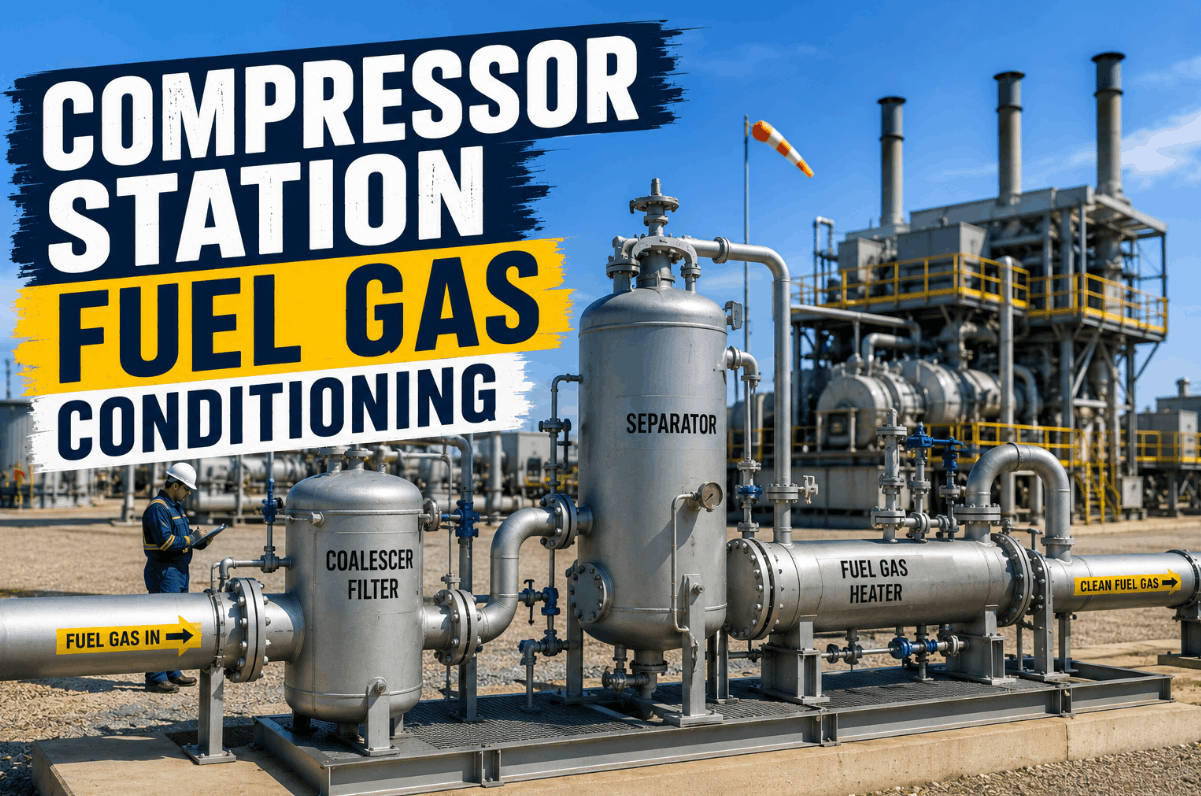
A compressor station's gas turbine or reciprocating engine is only as reliable as the fuel gas reaching its combustion chamber. Raw fuel gas pulled off a pipeline tap carries free liquids, condensed hydrocarbons, compressor oil carryover, pipe scale, and corrosion particulates — none of which are visible until they erode a fuel control valve, plug an injector, or trigger an unplanned trip during a load swing. OEM fuel specifications exist for a reason: turbines need gas superheated 20 to 30°C above the hydrocarbon dew point and held within a defined Wobbe Index band, while reciprocating engines are just as intolerant of liquid slugs reaching the carburetor or gas admission valves. A properly built filter, coalescer, separator, and heater train is the difference between a compression asset that runs its full service interval and one that is down for an emergency fuel nozzle replacement. Book a Demo to see how iFactory tracks fuel gas conditioning performance across your station fleet.
Why Fuel Gas Quality Determines Compression Asset Reliability
Most compressor station fuel gas is a slipstream off the same pipeline the station is compressing, which means it carries the same contamination risks as the sales gas itself — only now that gas is feeding a combustion engine instead of being transported downstream. Even minute quantities of liquid droplets or solids entering a turbine combustor can damage hot-section components and void OEM warranty coverage. Reciprocating engines face a parallel risk: liquid carryover reaching the fuel valve or gas admission system causes erratic combustion and accelerated wear. The conditioning train exists to remove that risk before it ever reaches the machine.
The Five Stages of a Complete Fuel Gas Conditioning Train
A fuel gas conditioning skid is not a single device — it is a sequence of unit operations, each protecting against a different failure mode. Skipping or under-sizing any one stage shifts the contamination burden downstream onto the combustion equipment itself.
Inlet Knockout / Separator
Removes bulk free liquids — condensate, compressor lube oil, and slugged water — before the gas reaches finer filtration stages. Protects downstream coalescer elements from premature loading.
Coalescing Filtration
Captures submicron liquid aerosols and solid particulates the separator stage cannot catch, reducing outlet liquid loading to under 0.1 ppm by weight and protecting fuel nozzles from erosion.
Pressure Reduction Manifold
Steps the pipeline tap pressure down to the turbine or engine's required fuel supply pressure. Rapid pressure drop encourages hydrate formation, which is why heating is sequenced around this stage.
Fuel Gas Superheater
Electric or indirect-fired heaters raise gas temperature above the hydrocarbon and water dew points by the OEM-specified superheat margin, ensuring no condensation occurs before the combustion chamber.
Final Filtration & Metering
A last filter stage catches any residual particulate before flow measurement and delivery to the turbine or engine fuel module.
Matching Fuel Gas Quality Parameters to Combustion Equipment Risk
Turbines and reciprocating engines fail differently when fuel gas quality drifts, which is why the conditioning train's monitored parameters need to map directly to the failure mode they prevent. Book a Demo.
| Fuel Quality Parameter | Monitoring Point | Failure Mode Prevented | Equipment Most Sensitive |
|---|---|---|---|
| Coalescer Differential Pressure | Across coalescer element, typically 1–3 psi clean | Element bypass, liquid carryover to downstream stages | Turbines and recip engines equally |
| Filter Differential Pressure | Across filter element, 3–8 psi clean rising to 15–25 psi | Particulate breakthrough, nozzle and valve erosion | Turbine fuel nozzles, recip gas admission valves |
| Superheat Margin | Gas temperature vs. calculated hydrocarbon dew point | Condensation in fuel lines, autoignition risk | Gas turbines — most sensitive to liquid carryover |
| Wobbe Index / TCWI | Heating value relative to specific gravity, temperature-corrected | Flashback, blowout, combustion dynamics instability | Gas turbines — OEM bands typically ±10% of design |
| Knockout Drum Liquid Level | Level switch with automatic drain activation | Liquid slugging into the coalescer or downstream piping | Recip engines — most sensitive to liquid slugs |
Why Differential Pressure Trending Catches Fuel Train Problems Early
Most fuel gas conditioning failures do not arrive as a sudden surprise — they arrive as a slow drift in differential pressure that nobody is watching closely enough between scheduled element changes. A coalescer element loading up shows rising DP weeks before it bypasses; a filter approaching its replacement threshold shows the same pattern. The problem in most stations is not that this data does not exist — it is that the gauge readings are logged on a clipboard during a daily round and never trended against the element's expected loading curve.
A technician on a daily round notes the coalescer DP is 4 psi today, up from 3 psi last week. On paper, that single reading looks unremarkable — it's still well under the 15–25 psi replacement threshold. What the clipboard does not show is that the rate of increase has accelerated compared to the prior six months, which is the actual early warning signal of upstream liquid loading or a developing leak. iFactory ingests every DP, temperature, and level reading from the conditioning skid continuously, trending each against the asset's own historical loading curve so a change in rate — not just an absolute threshold breach — triggers the maintenance flag. Book a Demo.
The iFactory Approach to Fuel Gas Conditioning Analytics
iFactory does not replace your fuel gas conditioning skid vendor or your existing PLC-based skid controls — it sits on top of them, turning scattered gauge readings and skid alarms into a connected, trended record across every compressor station in your fleet.
Continuous DP and Temperature Trending
Every coalescer, filter, and superheater reading is logged continuously and compared against each asset's own historical loading curve, not a generic fleet-wide threshold.
Superheat Margin Verification
Outlet gas temperature is continuously checked against the calculated hydrocarbon dew point for current gas composition, flagging margin erosion before condensation risk develops.
Element Replacement Forecasting
DP trend rate is used to forecast when a coalescer or filter element will reach its replacement threshold, supporting planned swaps instead of reactive ones.
Fleet-Wide Fuel Train Visibility
Reliability engineers managing multiple compressor stations get one dashboard showing every conditioning skid's status, rather than checking individual station logs separately.
"We had a recip engine taking a liquid slug every few weeks and nobody could explain why, because the knockout drum level switch logs were on a paper sheet nobody cross-referenced against the upstream pressure cycling. Once we got DP and level data trending continuously, the pattern was obvious within a month — and the fix was a simple drain timer adjustment, not an engine overhaul." — Reliability Engineer, Midstream Compression Operator
Conclusion: Fuel Gas Conditioning Is Asset Protection, Not Just Compliance
A filter, coalescer, separator, and heater train is frequently treated as a piece of balance-of-plant equipment rather than a frontline protection system for the most expensive rotating asset at the station. That framing is backwards. Every turbine fuel nozzle, every recip gas admission valve, and every hot-section component downstream of the conditioning skid is only as protected as that skid's actual, current performance — not its nameplate design specification. Continuous DP trending, superheat margin verification, and fleet-wide visibility turn the conditioning train from a once-a-shift gauge check into a genuine early-warning system for the combustion equipment it exists to protect.
Frequently Asked Questions: Fuel Gas Conditioning Systems
What does a fuel gas conditioning train typically include?
An inlet knockout/separator, coalescing filtration, a pressure reduction manifold, a superheater, and a final filter/metering stage, sequenced to remove liquids, solids, and to control temperature and pressure.
Why do gas turbines need fuel superheated above the dew point?
Condensed liquid reaching the combustor can cause flashback or autoignition issues; OEMs typically specify 20–30°C of superheat margin above the calculated hydrocarbon dew point.
How is coalescer or filter element condition normally tracked?
Through differential pressure monitoring — clean DP is typically 1–3 psi for coalescers and 3–8 psi for filters, rising to 15–25 psi as the trigger for element replacement.
Are reciprocating engines as sensitive to fuel quality as turbines?
Differently sensitive — recip engines are most vulnerable to liquid slugs reaching gas admission valves, while turbines are more sensitive to dew point margin and Wobbe Index stability.
Does iFactory replace the fuel gas skid's existing PLC controls?
No — iFactory ingests data from your existing skid controls and instrumentation to provide trending, forecasting, and fleet-wide visibility on top of the equipment you already operate.