Human factors engineering has emerged as the most critical yet most overlooked discipline in oil and gas operations, where a single moment of operator misjudgment can trigger events costing billions in damages, environmental catastrophe, and loss of life. Despite accounting for 60 to 80 percent of all major incidents, human error reduction still receives a fraction of the investment that goes into equipment reliability. The problem is that most operators treat human performance as a training issue when it is actually a design issue. The systems, procedures, interfaces, and work environments people operate within determine performance far more than individual competence. Understanding how cognitive workload, fatigue, and control room architecture intersect to create error-prone conditions is the first step toward building operations that protect people by design. Book a demo to explore how iFactory integrates human factors intelligence into operational command.
Design Operations That Protect People by Default, Not by Chance
iFactory embeds human factors engineering principles into every layer of your operational intelligence, from control room interface analytics to fatigue-aware scheduling and procedure compliance monitoring.
Where Human Error Originates in Oil and Gas Operations
Every major incident investigation in the oil and gas industry over the past four decades, from Piper Alpha to Texas City to Deepwater Horizon, has identified human factors as a contributing factor. Yet the industry continues to invest disproportionately in hardware safeguards while treating human performance as an afterthought. Research from the Energy Institute and multiple regulatory bodies shows that the root causes of human error are not random individual failures but predictable systemic conditions that can be engineered out of operations. The following data represents the percentage of major oil and gas incidents where each human factors deficiency was identified as a primary or significant contributing factor, drawn from aggregated analysis of over 300 incident investigations across upstream, midstream, and downstream operations.
These seven factors do not operate in isolation. An operator responding to an abnormal situation at 03:00 during a 12-hour night shift is simultaneously affected by cognitive overload, fatigue, and potentially inadequate procedures that were not designed for the specific scenario unfolding. The compounding effect means that addressing any single factor in isolation yields marginal improvements, while a systematic human factors engineering program that addresses all seven simultaneously can reduce human-error-related incidents by 40 to 60 percent based on published benchmarks from operators who have implemented comprehensive HFE programs.
Five Interconnected HFE Domains That Prevent Catastrophic Failure
Human factors engineering in oil and gas is not a single discipline but an integrated system of five domains that must work together. Each domain addresses a different layer of the human-system interaction, from the physical layout of the control room to the cognitive demands placed on operators during high-stress scenarios. When these domains are designed in isolation, which is the typical industry approach, they create gaps where errors propagate. When they are designed as an integrated system, they create defense-in-depth against human error. The following framework shows how these five domains connect and reinforce each other to form a complete human factors protection system for oil and gas operations.
The critical insight from this framework is that each domain creates conditions that either amplify or dampen the effectiveness of the others. A perfectly designed control room cannot compensate for poorly written procedures. World-class alarm management cannot overcome operator fatigue. Effective human factors engineering requires all five domains to be addressed as a unified system, which is precisely the approach iFactory takes when building operational intelligence layers for oil and gas clients.
The Five-Layer Control Room Design Hierarchy
Control room design in oil and gas facilities follows a hierarchical principle where each layer builds upon the one below it. Decisions made at the facility context level constrain what is possible at the room layout level, which in turn constrains workstation geometry, console design, and finally HMI screen layout. Most control room design failures occur because decisions are made at the wrong level, such as selecting HMI graphics standards before resolving room layout and viewing angle requirements. The following hierarchy shows the correct design sequence from macro to micro, with each layer defining the design constraints for the layer below it.
The most common design failure in oil and gas control rooms is starting at Layer 5, the HMI graphics, without having established the room layout and viewing geometry in Layers 1 through 3. This results in operators who must crane their necks to see critical information, screens that are too small for the viewing distance, and team communication patterns that are disrupted by poor spatial arrangement. A properly executed HFE program always starts from Layer 1 and works downward, ensuring that each level of design creates the optimal conditions for the level below it.
Cognitive Workload Intensity Map Across Operational Scenarios
Cognitive workload is not a single dimension but a combination of mental demand, time pressure, information volume, decision complexity, and communication load that varies dramatically across different operational scenarios. Understanding these variations is essential because operator performance degrades predictably as cognitive workload approaches and exceeds cognitive capacity. The following heat map shows the relative intensity of each demand dimension across five common oil and gas operational scenarios, based on NASA-TLX assessment data collected from control room operators across multiple refinery and production facility studies.
The heat map reveals a critical design insight: the scenarios where operators are most likely to make errors, emergency shutdowns and simultaneous alarm floods, are precisely the scenarios where cognitive demand across all dimensions reaches extreme levels simultaneously. This means that control room designs, procedures, and support systems optimized for routine operations will fail catastrophically when they are needed most. Effective human factors engineering explicitly designs for the highest-demand scenarios, not the average ones, by building in automation assistance, decision support tools, and reduced-information displays that lower cognitive demand during the moments when operator capacity is most constrained.
The 24-Hour Fatigue Risk Cycle in Continuous Operations
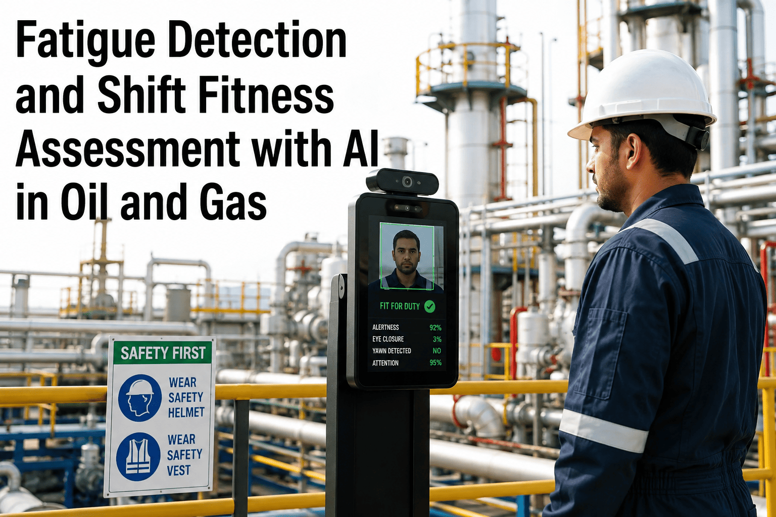
Fatigue in oil and gas operations is not a binary state but a continuously varying risk factor that follows predictable patterns aligned with circadian physiology, shift timing, and cumulative hours worked. The following timeline shows how fatigue risk levels change across a typical 12-hour night shift, from 18:00 to 06:00, based on biomathematical fatigue modeling validated against actual operator performance data from offshore platforms and onshore refineries. Understanding this cycle allows organizations to implement targeted interventions at the highest-risk windows rather than applying uniform mitigation measures that waste resources during lower-risk periods.
The 03:00 to 05:00 window represents the highest-risk period in any 24-hour operation, and this is where the majority of fatigue-related errors in oil and gas have been documented to occur. Effective fatigue risk management systems do not simply prohibit night shifts, which is operationally impractical for continuous processes, but instead implement a layered set of countermeasures that are specifically activated during this high-risk window. These include mandatory peer verification of critical actions, reduced task complexity during the circadian nadir, additional staffing to distribute workload, and automated monitoring systems that compensate for reduced human vigilance. The goal is not to eliminate fatigue, which is impossible in continuous operations, but to manage the risk it creates through design and scheduling interventions that reduce the probability and consequence of fatigue-related errors.
Seven-Step Procedure Design Process That Operators Actually Follow
Procedure non-compliance in oil and gas operations is rarely a willful act of disobedience. In the majority of cases, operators deviate from procedures because the procedures themselves are poorly designed, difficult to follow under operational stress, or do not match the actual conditions encountered in the field. The following seven-step process represents the HFE best practice for developing procedures that operators trust and follow, derived from EEMUA 201 and API RP 754 guidance adapted for modern digital procedure delivery environments.
The most important principle in this process is that procedure quality is measured by operator performance during validation, not by compliance with formatting standards. A procedure that perfectly follows every formatting rule but causes operators to hesitate, skip steps, or improvise workarounds is a failed procedure regardless of how well it is written. iFactory monitors procedure execution patterns across operations to identify where procedure design is creating friction, enabling continuous improvement that is grounded in actual operator behavior data rather than subjective expert opinion.
The Shift Handover Funnel: Where Operational Intelligence Disappears
Shift handover is the single highest-risk human factors event in continuous oil and gas operations, yet it receives less engineering attention than almost any other operational process. Research published in the Journal of Loss Prevention and multiple HSE studies has documented that information loss during shift handover follows a predictable funnel pattern where operational intelligence degrades at each stage of the handover process. The following visualization shows the percentage of total operational information that survives at each stage, based on studies conducted across 15 offshore platforms and 8 refinery control rooms.
The most dangerous stage of this funnel is not the initial loss during logging, which is relatively small at 18 percent, but the progressive degradation from verbal communication through to retention, where nearly half of all known information is lost. This means that an incoming operator begins their shift with less than one-third of the operational context that the outgoing operator possessed, and most of what was lost was contextual and qualitative information that is difficult to capture in structured log formats, such as the current stability of a controller loop that is oscillating but within alarm limits, or the fact that a specific valve has been sticking during the previous shift but has not yet failed. Structured handover tools that force systematic coverage of critical information categories, combined with digital systems that pre-populate handover checklists with real-time process data, can narrow this funnel significantly by reducing reliance on human memory and verbal communication for information transfer.
Human Reliability Analysis Methods Compared for Oil and Gas Applications
Human Reliability Analysis provides the quantitative foundation for human factors engineering by predicting the probability of human error for specific tasks under defined conditions. Multiple HRA methods exist, each with different strengths, data requirements, and levels of analytical rigor. Selecting the wrong method for a given application leads to either over-engineering, which wastes resources on low-risk tasks, or under-engineering, which leaves high-risk tasks without adequate human error defenses. The following comparison covers the four most widely used HRA methods in oil and gas applications, evaluated against the criteria that matter most for practical implementation in operating facilities.
| Method | Full Name | Best Suited For | Data Requirements | Predictive Accuracy | Implementation Effort |
|---|---|---|---|---|---|
| THERP | Technique for Human Error Rate Prediction | Task-level analysis of procedural operations with discrete action steps | Task decomposition, PSF definitions, error probability tables from SWREG | Moderate, strong for routine tasks, weaker for novel scenarios | High, requires trained analysts and extensive task modeling |
| HEART | Human Error Assessment and Reduction Technique | Rapid screening of error probability across multiple task types | Generic task type selection, Performance Shaping Factor multipliers | Low to moderate, useful for comparative analysis rather than absolute prediction | Low to moderate, can be applied by engineers with basic HFE training |
| CREAM | Cognitive Reliability and Error Analysis Method | Complex scenarios requiring cognitive modeling of operator decision-making | Contextual control model assessment, cognitive function analysis | Moderate to high for cognitive errors, requires expert judgment calibration | High, requires deep understanding of cognitive psychology and process operations |
| SLIM | Success Likelihood Index Methodology | Tasks where empirical data is scarce and expert judgment must substitute | Expert panel assessment of PSFs, rating scale calibration | Variable, highly dependent on expert panel quality and calibration rigor | Moderate, requires facilitated expert sessions and statistical processing |
In practice, most oil and gas operators benefit most from a tiered approach that uses HEART for initial screening to identify tasks with the highest human error probability, then applies THERP for detailed analysis of those high-priority tasks, and reserves CREAM for the most cognitively demanding scenarios such as emergency response and novel upset conditions where decision-making errors are the primary concern. This tiered approach concentrates analytical resources where they deliver the greatest risk reduction while avoiding the cost of applying the most rigorous methods to every task regardless of its risk significance. iFactory integrates HRA insights into its operational intelligence platform by mapping predicted error probabilities to actual operational data, enabling continuous validation and refinement of human error models based on real-world performance.
Common Questions About Human Factors Engineering in Oil and Gas
How does human factors engineering differ from traditional safety management systems in oil and gas?
Traditional safety management systems focus on establishing rules, procedures, and audit mechanisms that assume human compliance will follow from proper documentation and enforcement. Human factors engineering takes a fundamentally different approach by recognizing that human behavior is a product of the system design, not just individual discipline. Where a traditional SMS might respond to a procedural violation by retraining the operator and adding a compliance checkpoint, HFE responds by redesigning the procedure to eliminate the ambiguity that led to the deviation, modifying the interface to make the correct action more intuitive, or adjusting the workload to reduce the conditions that made the error likely. The shift is from blaming individuals for failing to comply with imperfect systems to designing systems that make compliance the path of least resistance. Book a demo to see how iFactory operationalizes this approach.
What is the typical return on investment for a human factors engineering program in a refinery or production facility?
Published case studies from major operators who have implemented comprehensive HFE programs report returns ranging from 5:1 to 15:1 over a three to five year period, measured through reduced incident costs, improved production uptime, lower turnover among control room operators, and decreased regulatory penalties. The largest single contributor to ROI is typically the reduction in unplanned shutdowns caused by human error, where a single avoided event can justify the entire HFE program cost. Secondary benefits include reduced training time for new operators because well-designed procedures and interfaces are faster to learn, reduced alarm flood frequency which decreases operator stress and turnover, and improved regulatory compliance that avoids fines and consent decree requirements. Contact support for ROI modeling specific to your operation.
Can human factors engineering be applied to existing facilities or only to new-build projects?
While the greatest impact is achieved when HFE is integrated from the earliest design stages of a new facility, significant improvements can be achieved in existing operations through targeted interventions that do not require capital-intensive modifications. The highest-impact modifications for existing facilities typically include alarm rationalization and management system upgrades, procedure redesign using the seven-step process, shift handover tool implementation, fatigue risk management system deployment, and HMI graphic modernization. These interventions primarily require analytical work and software changes rather than physical construction, making them feasible within operating budgets. Physical modifications such as console replacement, lighting upgrades, and room layout changes can be phased into planned turnaround schedules to spread costs. Book a demo to explore phased HFE implementation options.
How does iFactory specifically address human factors engineering within its operational intelligence platform?
iFactory addresses human factors engineering through multiple integrated capabilities rather than treating it as a separate module. The platform monitors operator interaction patterns with HMI screens to identify interfaces that create excessive navigation or cognitive load. It tracks procedure execution timing and deviation patterns to flag procedures that operators struggle to follow. It correlates incident and near-miss timing with shift schedules and fatigue risk models to identify fatigue-related risk windows. It analyzes alarm response times and acknowledgment patterns to detect alarm flooding and desensitization. It monitors shift handover duration and content coverage against structured handover checklists. All of these human factors indicators are surfaced alongside production, safety, and maintenance data in the command center, ensuring that human performance is treated as an equal operational dimension rather than a separate silo. Contact support for detailed capability mapping.
What qualifications should a human factors engineer have for oil and gas work, and how large should an HFE team be?
Effective human factors engineers in oil and gas typically hold advanced degrees in human factors engineering, cognitive psychology, or ergonomics, supplemented by specific training in process safety management, ISA-101 HMI design, EEMUA 191 alarm management, and API 754 process safety metrics. The most critical qualification is practical experience in operating facilities, as academic knowledge alone is insufficient to navigate the operational constraints, regulatory requirements, and organizational dynamics of oil and gas environments. Team size depends on portfolio scale, but a typical program for a single refinery requires one to two dedicated HFE professionals supported by part-time contributions from operations, engineering, and safety personnel. For multi-site portfolios, a center-of-excellence model with three to five HFE professionals providing governance, standards, and specialized analysis while site-level champions handle routine implementation is the most effective structure. Book a demo to discuss HFE team structure for your organization.
Stop Relying on Human Vigilance. Start Engineering Human Reliability Into Your Operations.
iFactory gives your leadership team real-time visibility into the human factors that determine whether your operators succeed or fail when it matters most, from cognitive workload monitoring to fatigue risk scoring to procedure compliance tracking across every site you operate.