A boiler feed pump trip during full load is one of the fastest ways a power plant loses its afternoon, yet the failure almost never starts at the moment the trip alarm sounds. Long before a mechanical seal starts leaking or a wear ring seizes against the impeller, the pump has been running through a slow, measurable decline that most plants only start watching once vibration or bearing temperature has already crossed a fixed alarm point. Condensate pumps, boiler feed pumps, and heater drain pumps each fail in their own characteristic way, driven by cavitation at low NPSH margin, thermal shock during start and stop cycles, and the wear ring erosion that comes from running off the best efficiency point. iFactory turns the vibration, temperature, and performance data your plant already collects into an early, asset-specific view of exactly where these pumps currently sit on that decline curve, and you can book a demo to see it applied directly to your own feedwater train.
Stop Losing Feedwater Train Pumps to the Same Three Failure Modes
Cavitation, seal wear, and wear ring clearance loss account for the overwhelming majority of unplanned condensate pump, boiler feed pump, and heater drain pump failures, and every one of them leaves a measurable trail in vibration, temperature, and performance data weeks before the pump actually trips offline.
Why a Condensate Pump, a Boiler Feed Pump, and a Heater Drain Pump Wear Out Differently
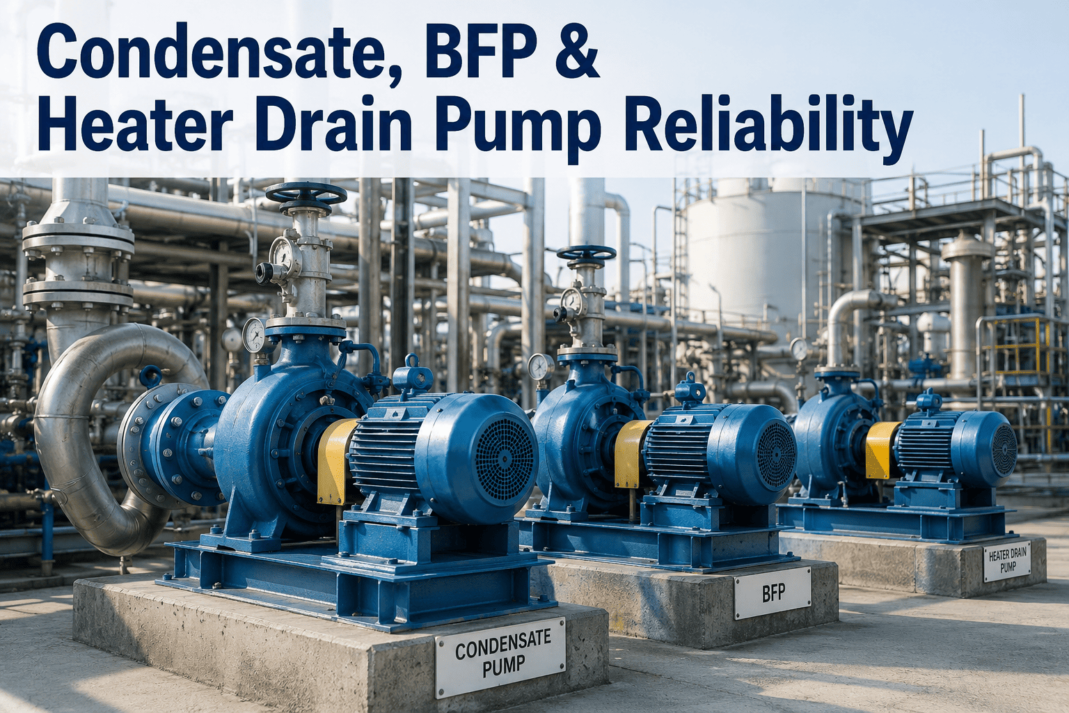
Treating every rotating asset on the feedwater train as one generic pump is the fastest way to miss the failure that is actually coming, because each of these three services puts a different kind of stress on the impeller, seal, and bearings, and a single fleet-wide alarm setting will always be wrong for at least one of them. The breakdown below separates the dominant failure mode and root cause for each pump type so your reliability program can prioritize the right monitoring signal on the right asset instead of applying the same vibration alarm threshold and inspection interval across three fundamentally different services.
The common thread across all three is suction margin. A condensate pump lives closest to vapor pressure at all times, a heater drain pump inherits the same risk whenever heater level control swings, and a boiler feed pump only sees this problem indirectly, through a starved suction from an upstream condensate or booster pump that has already started cavitating. Treating the feedwater train as a single chain rather than three isolated assets is usually what separates a reliability program that catches the real root cause from one that keeps replacing the same wear parts every outage without ever fixing the upstream driver.
Five Stages Every Pump Failure Passes Through Before It Trips
Reliability engineers call this the P-F curve: the distance between the point where a potential failure first becomes detectable and the point where the pump can no longer perform its function, and the width of that window is exactly what determines whether a repair happens during a planned outage or during an unplanned trip. Watching only the last one or two stages means accepting the shortest possible warning window, while a program built around the earliest measurable signals turns the same failure into a planned repair instead of an unplanned trip that pulls a crew off other work at the worst possible time.
Micro-Shift in Vibration Signature
A change as small as a few microns in bearing vibration amplitude or spectrum reveals emerging imbalance, misalignment, or the earliest stage of bearing degradation, long before anything is audible on the floor or visible on a standard trend chart.
Bearing Temperature and Motor Current Drift
Bearing temperature begins climbing, thrust pad wear accelerates, and motor current signature shifts as the degradation becomes measurable at multiple points simultaneously, narrowing the intervention window from months to weeks.
Efficiency Loss and Cavitation Onset
Suction pressure margin thins, vapor bubbles begin forming and collapsing on the impeller, and efficiency at rated flow can drop as much as 20 percent while the pump is still technically meeting its duty point.
Seal Leakage and Audible Symptoms
Mechanical seal flush flow becomes erratic, visible leakage begins, and the pump starts producing the crackling or knocking sound operators associate with a unit that is close to needing an outage-driven repair.
Functional Failure
The pump can no longer hold discharge pressure, maintain flow, or run without tripping on high vibration or bearing temperature, and the repair now requires a full teardown instead of a planned wear part replacement.
Most plants have instrumentation capable of seeing stages one through three today, but that data typically lives in a historian or a handheld vibration collector rather than in a system that continuously compares it against each pump's own healthy baseline and flags the point where the trend genuinely turns. Closing that gap is what moves the average intervention point earlier on the curve without adding a single new sensor to the pump.
Matching Seal Type to Service Condition Across the Feedwater Train
Seal selection is one of the biggest reliability levers on these pumps, and the wrong choice for a given service condition shows up as premature leakage, dry running damage, or repeated seal replacement during every outage. The table below maps common seal and bushing options to the service they suit best and the monitoring signal that gives the earliest warning of a problem.
| Seal or Bushing Type | Typical Service | Common Failure Trigger | Monitoring Signal |
|---|---|---|---|
| Soft Packing | Low-pressure condensate pumps, legacy installations | Gland over-tightening, loss of flush water flow | Steady weep rate change, packing gland temperature |
| Single Mechanical Seal | Condensate and heater drain pumps at moderate temperature | Dry running during low flow, misalignment-induced face wear | Seal chamber pressure drift, visible leakage onset |
| Dual or Tandem Seal, API 682 Plan 53 | Boiler feed pumps above 80°C service temperature | Barrier fluid pressure loss, thermal shock on frequent starts | Barrier fluid level and pressure trend |
| Labyrinth or Floating Ring Seal | High-pressure boiler feed pumps in ring section or barrel design | Warping after frequent stop and hot restart cycles | Sealing condensate injection flow and differential pressure |
| Metal-Filled Graphite Bushing | Vertical pumps in heater drain, hot well, and condensate service | Abrasive upset conditions, extended dry running | Internal clearance measured during scheduled inspection |
Seal selection decisions made ten or twenty years ago at commissioning often no longer match how the pump actually runs today, especially on units that have moved to more frequent cycling or lower average load than their original design point. Reviewing seal type against current operating pattern, not just original spec, is a low-cost step that frequently explains why one pump on an otherwise identical train keeps failing more often than its sister units.
Where a Variable Frequency Drive Actually Pays Back on Feedwater Pumps
A full-load feed pump running at fixed speed can only manage boiler demand below rated load by throttling a control valve or opening a recirculation line, wasting energy and adding mechanical stress every time the plant runs below full fire. Converting to variable speed control through a VFD changes the economics and the wear pattern of the pump at the same time, and the four benefits below are the ones reliability teams see first once a feed, condensate, or heater drain pump moves off fixed-speed operation.
A VFD conversion is not automatically the right call for every pump on the train. Units that already run near constant full load for most of the year see a smaller energy payback, and the retrofit cost still has to be justified against the specific failure history and duty cycle of that asset rather than applied as a blanket standard across the fleet.
Results From Feedwater Pump Reliability Programs on iFactory
The figures below are aggregated from plants monitoring condensate, boiler feed, and heater drain pumps on the iFactory platform, measured across multiple operating seasons after condition monitoring and PdM workflows went live, and are broken out here to show both the scale of the risk and the size of the improvement once the earliest stages of the degradation curve are actually being watched.