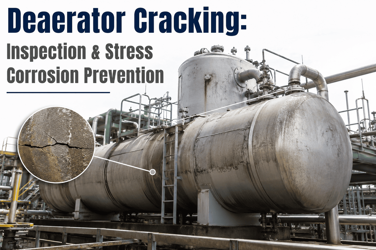
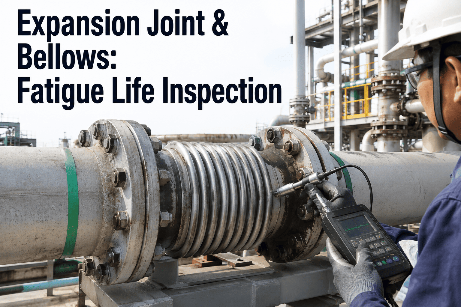
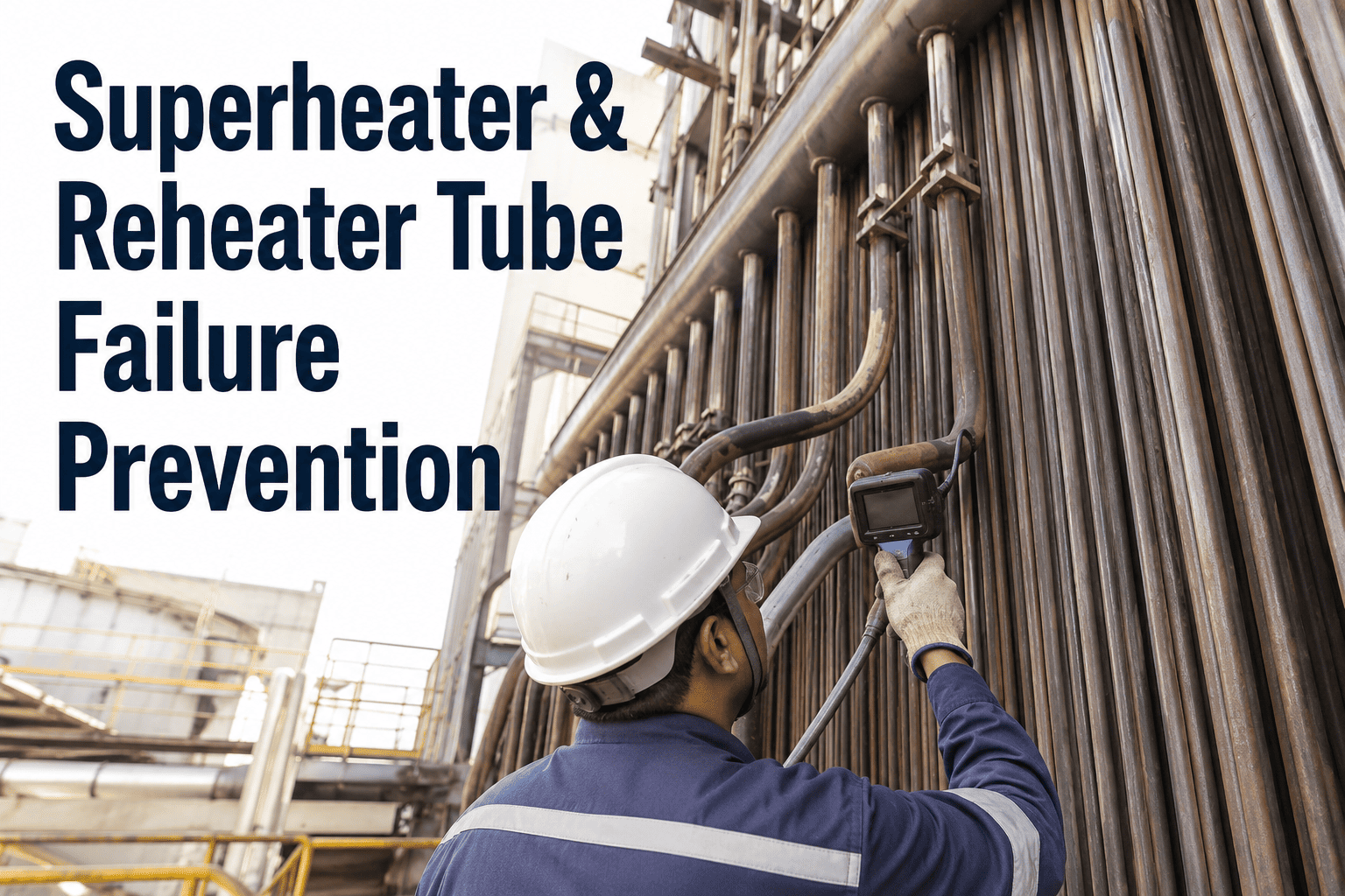
A deaerator failure is one of the few pressure vessel events in a power plant that has actually killed people, and it rarely comes with warning. Cracking has turned up in roughly a third to half of the industrial deaerators ever inspected, most of it hiding at the head-to-shell circumferential weld below the waterline, invisible from outside the vessel and easy to miss on a walk-by check. The mechanism is not exotic — thermal cycling, residual welding stress, and a mildly corrosive environment combine into corrosion fatigue and stress corrosion cracking that grows quietly until a shell splits. Book a demo to see how iFactory turns deaerator inspection history into a live cracking risk score instead of a paper file nobody reopens until something fails.
Pressure Vessel Integrity · Deaerator Cracking · Corrosion Fatigue
Deaerator Cracking: Why the Most Overlooked Vessel in the Plant Is Also the Most Dangerous
Stress corrosion cracking, weld toe cracking, and corrosion fatigue in deaerators follow known patterns at known locations. iFactory tracks every inspection finding against those patterns so nothing slips past two consecutive outages.
30-50%
Of industrial deaerators inspected have shown weld cracking
4-8 o'clock
Most common crack position on the head-to-shell circumferential weld
7 ppb
Target dissolved oxygen level a healthy deaerator should hold
12 mo
Typical maximum interval between internal weld inspections
Why Deaerators Crack
Three Mechanisms Behind Nearly Every Deaerator Failure
Deaerator cracking is not one phenomenon. Investigations going back to the fatal failures of the early 1980s consistently point to three mechanisms working together, and separating them matters because each one demands a different inspection response.
01
Residual Welding Stress
Fabrication leaves locked-in tensile stress at every weld seam, and that residual stress alone is often enough to start a crack once a mildly corrosive environment is present. Post-weld heat treatment reduces it but rarely removes it entirely, which is why the original weld seam stays the highest-risk zone for the life of the vessel. Even vessels fabricated to the same code and by the same shop can carry meaningfully different residual stress profiles depending on weld sequence, ambient temperature during fabrication, and how carefully the heat treatment cycle was controlled, which is one reason two sister units on the same site can show very different crack histories.
02
Thermal and Dynamic Cycling
Startups, shutdowns, and load swings drive rapid temperature differentials across the shell and internal trays. Water hammer from steam-water contact adds a dynamic shock component on top of that thermal cycling, and the combination fatigues the weld heat-affected zone far faster than steady-state operation ever would. Units that cycle daily to follow grid demand accumulate this fatigue damage at a materially higher rate than baseload units, which is a strong argument for setting inspection intervals based on actual cycling history rather than a single fixed calendar interval applied fleet-wide.
03
Corrosion-Assisted Crack Growth
Once a crack initiates, dissolved oxygen and feedwater chemistry accelerate its growth through corrosion fatigue rather than pure mechanical fatigue. Metallurgical samples pulled from cracked welds typically show a tightly bound oxide inside the crack itself, confirming corrosion is doing as much work as the stress. This is also why deaerator cracks tend to appear as multiple parallel indications rather than the single branched crack more typical of classic stress corrosion cracking, a distinction that matters when an inspector is deciding how thoroughly to scan the surrounding weld once one indication is confirmed.
Where to Look First
The Four Zones That Account for Most Deaerator Cracking
Cracking is not randomly distributed across a deaerator. Decades of inspection data from utilities, pulp and paper plants, and petrochemical facilities point to the same handful of locations every time, which is exactly what makes a targeted inspection program so much more effective than a generic full-vessel sweep.
Head-to-Shell Circumferential Weld
Highest Risk
The circumferential seam below the waterline, concentrated between the four and eight o'clock positions, carries the highest documented incidence of cracking of any location on the vessel, and it is also the hardest zone to access visually since it typically sits beneath internal trays and support structure that must be at least partially removed before an inspector can even reach the weld surface.
Longitudinal-to-Circumferential T-Junctions
High Risk
Wherever a longitudinal seam meets a circumferential seam, residual stress compounds from two directions at once, making the T-junction a recurring hot spot in failure investigations. Investigators reviewing historical failures have repeatedly singled out these junctions as the point where a crack is most likely to propagate quickly once it starts, since the stress field at the intersection is more complex than at any single straight seam.
Stainless Tray Enclosure Welds
Moderate-High Risk
The transition between stainless internals and the carbon steel shell creates a thermal expansion mismatch that stresses these welds every time the unit cycles temperature, and the mismatch is permanent by design since the two materials were chosen specifically for their different corrosion resistance properties rather than for matched expansion behavior.
Nozzle and Service Connection Welds
Moderate Risk
Feedwater inlet nozzles and other service connections see localized thermal shock that can seed cracks somewhat independently of the main shell seams, particularly where cold makeup water or condensate return enters the vessel and creates a sharp local temperature gradient against the surrounding hot shell metal.
What a Missed Crack Costs
The Real Consequences of Skipping a Deaerator Inspection Cycle
The catastrophic deaerator failures documented since the early 1980s were not isolated engineering curiosities. They were the reason the National Board, NACE, and TAPPI all issued formal inspection guidance in the first place, and the underlying risk has not gone away just because the guidance is now decades old. A shell that splits under pressure at operating temperature releases flashing steam and hot feedwater instantly, with no warning period comparable to a slow tube leak or a gradual bearing degradation trend. That is the specific reason deaerator cracking gets treated differently from most other pressure vessel wear mechanisms in a plant.
Unplanned Outage Duration
A deaerator taken out of service unexpectedly for weld repair or replacement typically forces a full unit derate or shutdown, since feedwater deaeration cannot simply be bypassed without risking downstream boiler tube pitting within days.
Downstream Equipment Damage
Oxygen breakthrough from a failing deaerator does not stay contained to the vessel itself. Elevated dissolved oxygen reaching the boiler accelerates tube pitting and weld cracking throughout the feedwater train, turning one component's problem into a fleet-wide chemistry excursion.
Personnel Safety Exposure
Deaerators operate at elevated pressure and temperature with a large stored energy content. The documented fatalities from historical shell failures are the reason internal inspection is treated as a safety-critical program rather than a routine maintenance line item.
iFactory Turns Every Deaerator Inspection Into a Trackable Risk Record.
Log NDE findings by weld zone, trend crack growth across outages, and get an automatic flag the moment a repaired area shows a repeat indication.
Inspection Methods
Which NDE Method Actually Finds Deaerator Cracks
Not every NDE technique is equally good at catching corrosion fatigue and stress corrosion cracking, which tend to be tight, fine, and clustered in parallel rather than branched. Choosing the wrong method is one of the most common reasons cracking gets missed until the next outage.
Method
Best For
Limitation
Wet Fluorescent Magnetic Particle (WFMT)
Tight, fine surface cracking typical of corrosion fatigue
Surface access and coating removal required
Liquid Dye Penetrant
Quick surface screening on accessible welds
Less sensitive than WFMT on tight cracks
Shear Wave Ultrasonic Testing
Sizing crack depth once a surface indication is found
Requires trained operator interpretation
Radiography
Confirming through-wall extent on suspect welds
Radiation safety controls and vessel downtime
Building the Program
A Four-Step Deaerator Cracking Inspection Cycle
The plants that stopped having surprise deaerator failures did not simply inspect more often. They built a repeatable cycle that connects each inspection to the last one instead of treating every outage as a blank slate.
1
Prepare and Access
Drain, clean, and gain physical access to the head-to-shell weld and tray enclosure welds before any NDE begins, since surface prep quality directly determines detection sensitivity. Removing internal trays and support brackets to reach the lower circumferential seam is often the single largest time investment in the entire outage, which is why access planning should start well before the unit actually comes offline.
2
Scan Known Hot Spots First
Run WFMT across the circumferential seam, T-junctions, and nozzle welds before a full-vessel sweep, so limited outage time goes to the zones most likely to actually show cracking. A full-vessel sweep can still follow once the known hot spots are cleared, but sequencing the highest-probability areas first protects the inspection against getting cut short by an outage schedule slip.
3
Size and Document Every Indication
Any confirmed indication gets sized with shear wave UT and logged with location, length, and orientation, creating the baseline the next outage will compare against rather than a pass or fail checkbox. Photographing the indication alongside a scale reference and recording the exact clock position turns a one-line inspection note into something a future team can actually reproduce and compare against.
4
Grind, Repair, and Re-Inspect
Cracks are removed by grinding and the ground area is reinspected before weld repair to confirm the crack is fully gone, since a repair over a residual crack tip almost guarantees a repeat finding. Remaining wall thickness should be measured after grinding and before rewelding to confirm the vessel still meets minimum required thickness at that location, not just that the visible crack indication is gone.
Standards and Documentation
Where NBIC and NACE Guidance Actually Applies to Your Program
Deaerator inspection guidance did not emerge from a lab, it emerged directly from the fatal shell failures reported in 1982 and 1983, which prompted the National Board of Boiler and Pressure Vessel Inspectors, the National Association of Corrosion Engineers, and TAPPI to issue formal technical advisories on internal weld inspection. Those advisories still form the practical basis for most utility and industrial deaerator programs today, and the National Board Inspection Code continues to reference deaerator cracking as a distinct, named degradation mechanism rather than treating it as generic pressure vessel wear.
National Board Inspection Code (NBIC)
Provides the inspection and repair framework jurisdictional inspectors expect a plant to follow, including documentation of weld repairs and the qualification requirements for the personnel performing NDE.
NACE / AMPP Corrosion Guidance
Covers the water chemistry control targets, including dissolved oxygen limits, that directly slow the corrosion fatigue growth rate at existing crack sites and reduce the likelihood of new crack initiation.
Original TAPPI Technical Advisories
Among the first formal documents to connect deaerator shell failures to specific weld locations and cyclic operating conditions, still cited in modern root cause investigations of new failures.
None of these documents replace a plant's own inspection judgment, but a program that cannot point to which standard's interval and method requirements it is following tends to struggle when a jurisdictional inspector, insurer, or corporate reliability audit asks the question directly.
Reactive vs. Tracked
Paper Inspection Records vs. a Tracked Cracking History
Question
Paper Records
Tracked History
Is this a repeat indication?
Depends on someone remembering the last report
Flagged automatically against the same weld zone's history
Is crack growth accelerating?
Only visible by pulling and comparing old PDFs
Trended across outages automatically
Which weld failed the repair?
Buried in a file cabinet or shared drive folder
Tied directly to the weld map and searchable instantly
When is the next inspection due?
Tracked manually against a spreadsheet
Scheduled automatically from the last finding's severity
From the Field
What a Repeat Crack Finding Actually Looks Like
We had ground out and repaired a crack on the same circumferential weld twice in six years before anyone connected the two events. Both times the finding got written up as a standalone repair, filed, and forgotten. It was only when we started keeping a running record by weld zone instead of by outage that we saw the pattern — same location, same orientation, growing faster the second time. That record changed how we scoped the next outage entirely, because we went in already knowing exactly where to look and what growth rate to expect.
— Fixed Equipment Engineer, Combined Cycle Power Plant
2 repairsOn the same weld zone before the pattern was caught
6 yearsGap between the two repairs, invisible without a tracked record
1 recordWeld-zone history that finally connected the two events
Conclusion
Deaerator Cracking Is Predictable. Most Programs Just Don't Track It That Way.
Deaerator cracking is one of the best-understood failure mechanisms in the pressure vessel world. The mechanisms are known, the high-risk weld zones are known, and the right NDE methods for finding tight corrosion fatigue cracks are well documented going back decades. What most plants lack is not knowledge of the mechanism, it is a record that connects one outage's findings to the next.
iFactory keeps every deaerator inspection finding tied to its weld zone, trends crack growth across outages, and flags a repeat indication before it becomes a repeat failure. Book a demo to see your own deaerator's inspection history mapped this way.
Frequently Asked Questions
Deaerator Cracking and Inspection — Common Questions
How often should a deaerator be internally inspected for cracking?
Most guidance from the National Board and NACE recommends an internal weld inspection at every annual outage for deaerators with any prior cracking history, and at minimum once every two to three years for units with a clean inspection record. Vessels that see frequent load cycling, startups, or shutdowns should default to the shorter interval regardless of past findings, since thermal and dynamic stress accumulate faster under cyclic operation. A vessel approaching thirty years of service, which is roughly when the historical incidence rate climbs sharply, is generally a strong candidate for the shorter interval even if it has never shown a confirmed indication.
Book a demo to see how inspection intervals can be set automatically from a unit's cycling history.
Can a cracked deaerator weld be repaired instead of replaced?
Yes, in the large majority of cases a cracked weld is repaired by fully grinding out the crack, reinspecting the ground area to confirm no crack tip remains, and rewelding with a qualified procedure. Vessel replacement is typically reserved for extensive cracking across multiple zones, through-wall cracking discovered late, or a shell that has already experienced significant wall loss from corrosion alongside the cracking. A repair should always be evaluated against the National Board Inspection Code's requirements for the specific repair type before work begins, since some repair scopes require a jurisdictional inspector's review and sign-off.
Why does dissolved oxygen control matter for cracking, not just corrosion?
Dissolved oxygen does not just cause general corrosion, it directly accelerates the corrosion fatigue mechanism that drives most deaerator cracking, since the crack growth rate depends heavily on the corrosive environment at the crack tip. Keeping dissolved oxygen at or below roughly seven parts per billion slows that growth rate substantially, which is why water chemistry control sits alongside NDE as a primary mitigation strategy rather than a separate concern.
What is the difference between stress corrosion cracking and corrosion fatigue in a deaerator?
Stress corrosion cracking tends to produce branched crack patterns and depends on a specific combination of alloy, environment, and sustained stress, while corrosion fatigue produces multiple tight parallel cracks driven by cyclic loading in a mildly corrosive environment rather than one specific chemical trigger. Deaerators experience mostly corrosion fatigue because of their constant thermal and pressure cycling, though both mechanisms can appear on the same vessel over its service life. Metallurgical sampling of a representative indication is the only reliable way to confirm which mechanism is actually driving a specific vessel's cracking, since the surface appearance of early-stage cracks from either mechanism can look very similar to the naked eye.
What should be documented after every deaerator inspection?
A complete inspection record should capture the exact weld zone and clock position of any indication, its length and orientation, the NDE method used to find and size it, whether it was a new finding or a repeat of a prior repair location, and the water chemistry and cycling history for the period since the last inspection. Without all five of these, the next inspection team is effectively starting over instead of building on prior data.
Contact support for help structuring a deaerator inspection record template.
Stop Losing Deaerator Crack History Between Outages
Track every weld zone, every finding, and every repair in one place, and let iFactory flag a repeat indication before it becomes the next failure investigation.