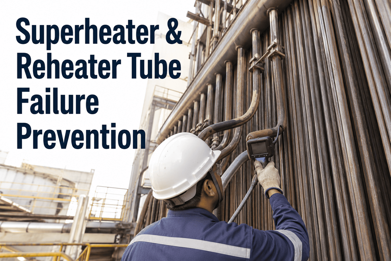
Superheater and reheater tubes operate at temperatures that push the metallurgical limits of the steel itself. Unlike waterwall tubes protected by boiling heat transfer, SH and RH tubes rely on steam cooling that provides far less heat absorption per unit area, leaving the tube metal closer to the flue gas temperature than any other boiler surface. This thermal position makes them the first components to fail when conditions drift above design limits, and a single failure often causes secondary damage through steam impingement to adjacent tubes. Understanding what drives these failures and how to monitor for them separates proactive tube life management from reactive outage patching. Explore how iFactory structures temperature and degradation tracking by visiting iFactory support.
Boiler Reliability · SH/RH Tube Life
Superheater and Reheater Tubes Fail First. Here Is How to Stop It.
The highest-temperature tubes in your boiler are also the most vulnerable. Temperature monitoring, oxide tracking, and structured sampling are the three tools that turn SH/RH tube life from a gamble into a managed number.
Operating Context
Why SH and RH Tubes Fail Before Waterwalls
The conditions SH and RH tubes endure are fundamentally different from waterwall tubes. Every row below shows why the same boiler environment produces drastically different failure risk depending on where the tube sits.
Creep Life
The Temperature-Life Relationship That Destroys Tubes
Creep rupture life is not a linear function of temperature. Based on the Larson-Miller parameter for common SH/RH materials, every small temperature increase above the design point removes a disproportionate share of remaining tube life. The bars below show why even minor temperature excursions are not minor at all.
Design Temperature
100% Remaining Life
+15°F Over Design
40% Remaining Life
+25°F Over Design
15% Remaining Life
+50°F Over Design
3% Remaining Life
+75°F Over Design
Less Than 1% Remaining Life
Values are representative for T22 and TP304H materials using the Larson-Miller parameter. Actual values vary by material grade, stress level, and operating pressure. The directional relationship holds across all ferritic and austenitic SH/RH tube grades.
Degradation Sources
Fireside and Steam-Side: The Two Directions Tubes Degrade
SH and RH tubes are attacked from both sides simultaneously. The fireside faces corrosive flue gas, molten ash deposits, and erosive particles. The steam-side faces oxide scale growth, hydrogen generation, and creep damage from sustained thermal stress. Ignoring either side means missing half the failure picture.
Fireside Attack
Molten Salt Corrosion
Alkali metals from the fuel combine with sulfur trioxide to form alkali trisulfates that are molten in the 1000-1150°F range. This molten salt dissolves the protective oxide layer on the tube surface, exposing fresh metal to continuous corrosive attack that produces smooth, external wall loss concentrated on the upstream face of the tube.
High-Temperature Oxidation
When flue gas temperatures exceed the threshold for protective oxide stability, the outer scale breaks down and re-forms in a cycle that consumes base metal with each cycle. This produces a thick, layered oxide scale on the external surface that can be visibly flaking during inspections and indicates active metal loss.
Coal Ash Corrosion
Fuels high in chlorine or certain sulfur compounds produce aggressive ash deposits that react with the tube surface at elevated temperatures. The corrosion rate depends on ash chemistry, deposit thickness, local gas temperature, and tube metal temperature, making it highly variable across different furnace zones and fuel sources.
Fly Ash Erosion
Particulate in the flue gas stream impinges on tube surfaces at high velocity, removing metal through mechanical abrasion rather than chemical reaction. Erosion patterns are directional and concentrated at specific locations where gas flow changes direction, such as at tube bends, headers, and leading edges of pendant tubes.
Steam-Side Attack
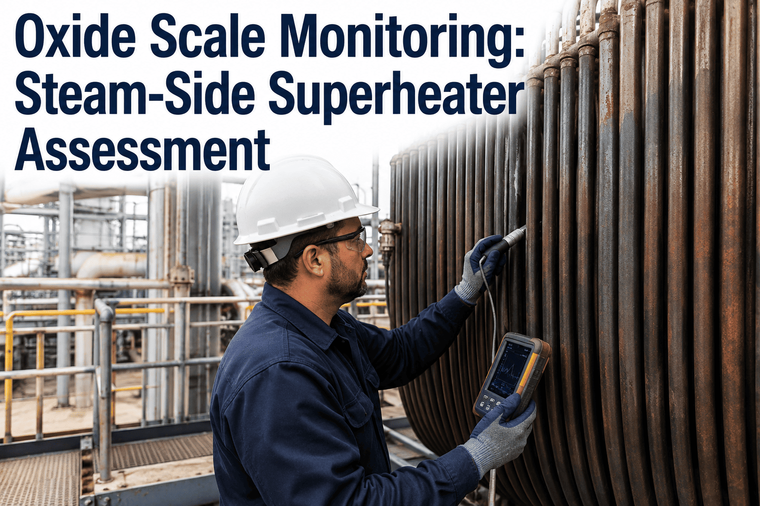
Internal Oxide Scale Growth
Steam reacts with the tube steel to form magnetite scale on the internal surface. This scale grows parabolically with time and exponentially with temperature, adding an insulating layer that raises the tube metal temperature further and accelerates both scale growth and creep damage in a self-reinforcing cycle.
Scale Exfoliation During Transients
Thick internal oxide has a different thermal expansion coefficient than the base metal. During startups, shutdowns, and load swings, the differential expansion causes the scale to crack and detach in flakes. These exfoliated pieces travel downstream, block tube bends and headers, cause localized overheating, and can damage turbine blades.
Creep Cavitation
Sustained operation above the creep threshold temperature causes grain boundary voids to nucleate and grow over time. These cavities link up to form microcracks that reduce load-carrying capacity long before any visible external sign appears. Cavitation is irreversible and accumulative, meaning every hour at elevated temperature permanently reduces remaining life.
Hydrogen Damage from Steam Reaction
The steam-iron reaction that forms internal oxide also releases atomic hydrogen. At normal operating conditions, most hydrogen is carried away by the steam flow. But under certain conditions, hydrogen can diffuse into the steel and cause decarburization and intergranular cracking, particularly at locations where scale has disrupted normal hydrogen transport.
Degradation Stages
From New Tube to Failure: The Six Phases of SH/RH Tube Life
Tube degradation is not a single event but a progression through identifiable stages. Recognizing which stage a tube is in determines whether you can safely defer replacement or need to act before the next startup.
Phase 1
Commissioning
Clean tube surface, full design wall thickness, no internal or external scale. The tube is at maximum structural capacity and the creep life clock begins ticking from the first hour at operating temperature.
Phase 2
Early Service
Thin protective oxide layers form on both the steam-side and fireside. Wall loss is negligible but the metallurgical clock is running. This is when baseline UT readings and tube samples should be collected for future comparison.
Phase 3
Mid-Life
Internal oxide scale reaches measurable thickness and begins affecting heat transfer. External corrosion or erosion may be producing detectable wall thinning. Scale thickness is approaching the range where exfoliation becomes possible during transients.
Phase 4
Advanced Degradation
Microstructural changes become detectable through metallurgical examination. Carbide spheroidization in ferritic steels or sigma phase formation in austenitic steels indicates the material has spent significant time above its threshold temperature. Creep cavities may be present.
Phase 5
End of Useful Life
Cavities have linked into microcracks. Wall thickness may be at or near the minimum required for design pressure. The tube can still operate for a limited period but the risk of sudden rupture increases with every additional operating hour at temperature.
Phase 6
Failure
Creep rupture produces a longitudinal crack with thick, fibrous edges. The high-pressure steam release can cause secondary damage to adjacent tubes through erosion and thermal shock, expanding the repair scope well beyond the original failure location.
Detection Methods
Four Monitoring Approaches That Catch Overheating Before Rupture
You cannot manage what you cannot measure. SH and RH tube temperature is the single most important variable for tube life, but it is also one of the most difficult measurements to make reliably inside an operating boiler. Each method below has strengths and gaps that complement the others.
Welded or peened thermocouples installed on selected tube surfaces provide continuous direct metal temperature readings during operation. They are the most accurate method available but cover only the specific tubes where they are installed, leaving the majority of the tube bank unmonitored. Thermocouple drift, attachment degradation, and lead wire damage in the high-temperature furnace environment require regular validation against portable measurements during outages.
Non-contact temperature measurement through boiler sight ports or inspection windows provides a broader view than point thermocouples but with lower accuracy. Pyrometer readings are affected by flue gas absorption, sight glass condition, tube emissivity variations, and the angle of measurement. Despite these limitations, pyrometry is valuable for identifying hot spots and spatial temperature patterns across tube banks that point thermocouples cannot see.
Steam Temperature Differentials
Monitoring the temperature difference between SH/RH inlet and outlet headers provides an indirect measure of average tube metal temperature. A rising differential over time can indicate increasing internal oxide scale thickness, which acts as insulation and forces the tube metal temperature higher to maintain the same steam outlet temperature. This method covers the entire circuit but cannot identify individual tube problems.
Outlet Header Temperature Mapping
Measuring steam temperature at individual tube outlet connections during an outage reveals which tubes are running hotter than others. Tubes with the highest outlet temperatures have either the thickest internal scale, the most severe fireside fouling, or a flow restriction. This mapping directly identifies the highest-risk tubes for closer inspection, UT thickness measurement, or replacement during the current outage.
Tube Sampling
How to Run a Tube Sampling Program That Actually Extends Life
Tube sampling is the only way to see what is happening inside the metal. UT measurements tell you about wall thickness. Thermocouples tell you about temperature. Only a metallurgical examination of an extracted tube sample tells you whether creep cavities are forming, carbides are spheroidizing, or the material is still within its design capability.
1
Select Target Circuits
Prioritize circuits with the highest outlet temperatures, the longest operating hours since last replacement, and any history of temperature excursions or fuel changes that could have accelerated degradation.
2
Choose Tube Locations
Extract samples from the highest-temperature tubes identified by outlet header mapping, not from convenient or accessible locations. Sampling a cool tube in a hot circuit provides data that is not representative of the actual risk.
3
Extract Proper Samples
Remove a full tube section spanning at least 12 inches, preserving both the fireside and steam-side surfaces. Record the exact orientation, elevation, and circuit position before cutting to maintain traceability from the lab report back to the furnace.
4
Conduct Laboratory Examination
Perform metallographic cross-sections to evaluate microstructure, measure internal and external oxide scale thickness, assess creep cavity density using established rating scales, and test mechanical properties if required by the assessment standard being applied.
5
Assess Against Criteria
Compare laboratory findings against established criteria such as EPRI guidelines, ASME recommendations, or OEM data sheets for the specific material grade. The assessment should produce a clear determination of whether the tube is in the early, mid, or late stage of its creep life.
6
Extrapolate to the Fleet
Apply the findings from sampled tubes to all tubes in the same circuit operating under similar conditions. Tubes with higher outlet temperatures or longer service hours than the sample should be assumed to be in equal or worse condition unless direct evidence proves otherwise.
Prevention Actions
Prevention Priorities Ranked by Impact on Tube Life
Not all prevention actions carry the same weight. Temperature control determines whether your tubes are operating on the designed life curve at all. Everything else extends or reduces the margin around that curve. The ranking below reflects the actual leverage each action has on SH/RH tube failure frequency based on industry failure data.
High Impact
Steam Temperature Control
Maintain SH and RH outlet temperatures within the design envelope during steady-state operation, startups, shutdowns, and load swings. Temperature overshoots during transients are often the largest single contributor to accumulated creep damage because the life fraction consumed per hour increases exponentially with temperature.
High Impact
Fuel Quality Management
Monitor and control sulfur, chlorine, alkali metal, and ash content in the fuel. Fuel switches or blends that introduce higher corrosive species can dramatically accelerate fireside corrosion rates on SH and RH tubes without any change in operating temperature, shortening life below original design expectations.
Medium Impact
Periodic Tube Sampling
Establish a recurring tube sampling schedule tied to operating hours and outlet temperature data. Sampling at regular intervals creates a degradation trend that enables remaining life projection rather than a single-point assessment that can only tell you where the tube is today, not where it is heading.
Medium Impact
Oxide Scale Thickness Tracking
Measure internal oxide scale thickness on each tube sample and track the growth rate across successive sampling intervals. When the scale approaches the thickness where exfoliation becomes likely, you can plan a cleaning or replacement action before exfoliated scale causes downstream blockages or turbine damage.
Foundational
Consistent Inspection Records
Maintain UT thickness data, temperature logs, sample results, and replacement records in a structured system that allows trend analysis across outages. Plants that rely on paper files or disconnected spreadsheets cannot perform the cross-referencing needed to identify patterns that predict future failures.
Foundational
Replacement Scope Optimization
Use thickness maps, outlet temperature data, and sampling results to define tube panel replacement boundaries that remove all at-risk material without unnecessarily replacing tubes that have significant remaining life. This requires integrating multiple data sources into a single decision view for each tube.
Your SH and RH Tubes Have a Finite Number of Hours at Temperature. Are You Counting Them?
iFactory tracks tube temperatures, oxide scale measurements, sampling results, and replacement history in a single system that projects remaining life and flags the tubes that need attention before the next outage.
Common Questions
Superheater and Reheater Tube Failure Prevention — Frequently Asked
How much does a 10-degree temperature excursion actually reduce SH tube life?
For ferritic alloys like T22, a sustained 10-15°F increase above the design metal temperature roughly halves the remaining creep rupture life based on the Larson-Miller parameter. For austenitic alloys like TP304H, the relationship is similar though the absolute temperature threshold is higher. The critical word is sustained, because a brief spike during a transient consumes far less life than the same temperature maintained for thousands of hours. The practical problem is that most plants do not have enough thermocouples to know whether an excursion affected one tube or an entire panel, so they must assume the worst case for life accounting purposes.
Book a demo to see how iFactory tracks temperature excursions against tube life consumption.
What is the difference between short-term and long-term overheating in SH tubes?
Short-term overheating occurs over minutes to hours, typically from a sudden flow blockage or loss of cooling, and produces a thin-edged rupture with little to no microstructural change because there was not enough time for creep damage to develop. Long-term overheating occurs over thousands of operating hours at temperatures above the creep threshold, producing a thick-edged longitudinal rupture with significant microstructural degradation including carbide spheroidization and creep cavitation. The corrective actions are completely different: short-term overheating requires finding and eliminating the flow restriction or operating anomaly, while long-term overheating requires either reducing the operating temperature, upgrading the material grade, or accepting a shorter replacement interval.
Contact support for help setting up mechanism classification for your tube failures.
When should internal oxide scale be a concern for SH and RH tubes?
Internal oxide scale becomes a concern on two fronts: its insulating effect on heat transfer and its potential to exfoliate. The insulating effect raises tube metal temperature, which accelerates both further scale growth and creep damage in a self-reinforcing cycle. Exfoliation becomes a risk when scale thickness exceeds approximately 10-15 mils, depending on the material and the severity of thermal transients. Exfoliated scale particles can block tube bends, restrict flow in header connections, cause downstream tubes to overheat and fail, and travel into the turbine where they cause blade erosion. Plants that do not measure scale thickness on tube samples are operating without knowing whether they have an exfoliation risk building inside their SH and RH circuits.
Book a demo to explore scale tracking in iFactory.
How often should superheater tubes be sampled for metallurgical examination?
Sampling frequency depends on the operating hours accumulated since the last replacement, the outlet temperature margin relative to design, and the results of previous samples. A common approach for high-temperature SH circuits is to sample at 50,000 to 80,000 hour intervals, with more frequent sampling if the previous examination showed mid-to-late stage creep damage. If a sample shows early-stage microstructural changes with significant remaining life, the interval can be maintained or extended slightly. If a sample shows late-stage cavitation, the entire circuit should be evaluated for replacement rather than waiting for the next sampling interval. The worst practice is to have no fixed sampling schedule and only extract a tube after a failure has already occurred.
Contact support to discuss setting up a sampling schedule for your units.
Can fireside corrosion on SH tubes be reduced without changing the fuel?
If the fuel composition cannot be changed, there are still several levers available. Coating technology using thermal spray or weld overlay materials like alloy 625 can provide a corrosion-resistant barrier on the most exposed tube surfaces, though the coating must be reapplied periodically as it degrades. Adjusting combustion to reduce local gas temperatures in the most corrosive zones can slow the corrosion rate, as can modifying soot blowing patterns to prevent deposit buildup that traps corrosive species against the tube surface. In some cases, repositioning tubes within the bundle to move the most vulnerable rows to a lower-temperature location can extend their life significantly. All of these approaches require knowing exactly where the corrosion is most severe, which comes from systematic thickness mapping and visual inspection data.
Book a demo to see how iFactory maps corrosion patterns across SH and RH circuits.
Every Hour at Excess Temperature Permanently Removes Creep Life You Cannot Get Back
Temperature tracking, oxide scale monitoring, tube sampling, life projection, and replacement planning, built for the way superheater and reheater tube programs actually run across a fleet.