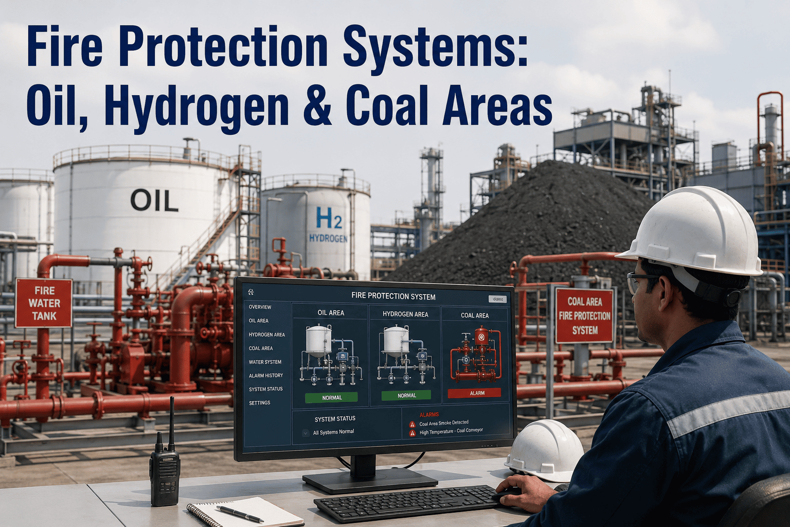
Power plants contain some of the most concentrated fire risk areas in any industrial facility — lubricating oil under high pressure near hot turbine surfaces, hydrogen gas circulating through generator seals at 500 kilopascals, pulverized coal dust accumulating on every horizontal surface in the conveying system, and mineral oil-filled transformers rated at hundreds of megavolt-amperes sitting adjacent to critical plant infrastructure. A fire in any one of these zones does not just damage equipment — it can force a unit trip, trigger cascading grid instability, and create life-safety scenarios that demand immediate evacuation. The fire protection systems protecting these areas must be designed, maintained, inspected, and documented with the same rigor applied to the plant's primary generating systems. To see how iFactory structures fire protection system management for your plant, book a 30-minute demo.
Fire Protection Systems in Power Plants: Oil, Hydrogen, Coal, and Transformer Areas
A zone-by-zone guide to fire detection, suppression, and system integrity management across the highest-risk areas in fossil, gas, and biomass generating stations.
Five Fire Risk Zones That Define Your Plant's Protection Strategy
Fire risk in a power plant is not uniform — it is concentrated in specific zones where fuel, oxygen, and ignition source converge under operating conditions that make ignition highly probable if protections fail. The five zones below represent the fire risk hierarchy in a typical fossil or combined cycle plant, ranked by the combination of ignition probability, fire growth rate, and consequence severity. Each zone demands a distinct combination of detection technology, suppression medium, and system configuration that matches its unique hazard profile.
Turbine Lube Oil System
The turbine lubricating oil system circulates thousands of gallons of mineral oil at pressures exceeding 200 psi through piping, bearings, filters, and coolers located directly beneath and adjacent to turbine surfaces operating at 1,000 degrees Fahrenheit or higher. A high-pressure oil leak atomizes into a fine mist that has an auto-ignition temperature as low as 420 degrees Fahrenheit — far below the temperature of nearby turbine casings and steam piping. Oil mist fires can develop from first ignition to full room involvement in under 60 seconds, overwhelming manual response capabilities. The fire protection system for this zone must detect oil mist at the earliest pre-ignition stage and deliver suppression agent within seconds of confirmed detection. NFPA 15 and NFPA 850 specifically address turbine lube oil fire protection with deluge spray systems using water or water-foam solution as the primary suppression medium.
Hydrogen-Cooled Generator and Seal Oil System
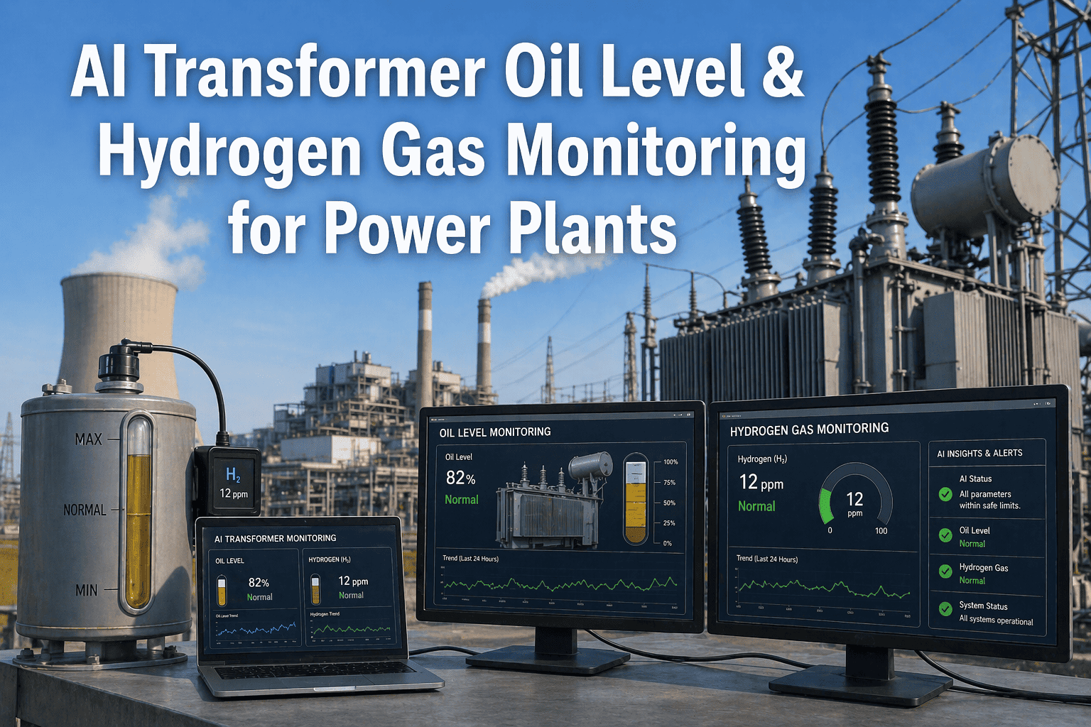
Hydrogen is used as a cooling medium in large turbine generators because of its superior heat transfer properties and low density. However, hydrogen has the widest explosive range of any industrial gas — it will ignite at concentrations from 4 percent to 75 percent in air, and its minimum ignition energy is just 0.017 millijoules, meaning a static discharge too small to feel can trigger an explosion. Hydrogen leaks at generator seal oil rings, at hydrogen cooler joints, or at sampling connections can create explosive atmospheres in the generator enclosure, the basement below the generator, and adjacent turbine deck areas. The fire protection challenge is compounded by the fact that hydrogen fires are nearly invisible in daylight and produce almost no smoke — conventional flame detectors may not see the flame, and conventional smoke detectors will not respond because there is no smoke. Dedicated hydrogen flame detectors using infrared or thermal imaging are required, along with continuous hydrogen concentration monitoring with automatic ventilation and purging systems.
Coal Handling and Pulverizing System
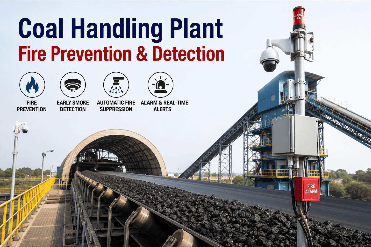
Coal handling areas — from the receiving dock through conveyor galleries, crusher houses, silos, and pulverizer mills — present a dust explosion hazard in addition to a surface fire hazard. Pulverized coal dust with a particle size below 75 microns can form explosive concentrations at just 35 grams per cubic meter of air. A primary explosion in a silo or mill can dislodge accumulated dust from structural surfaces, creating a secondary explosion that propagates through the entire conveying system with devastating force. Fire protection in coal handling requires a layered approach: temperature monitoring and CO detection for smoldering fires in silos and mills, spark and ember detection on conveyor belts, deluge or water spray systems for conveyor galleries, and explosion venting or suppression systems for pulverizers and silos. NFPA 120 and NFPA 850 provide specific requirements for coal handling fire protection that address both fire and explosion scenarios.
Power Transformers and Electrical Equipment
Large power transformers contain thousands of gallons of mineral oil that serves as both an insulating and cooling medium. An internal electrical fault — caused by insulation degradation, winding failure, or through-fault damage — can generate enough energy to rupture the transformer tank, ejecting oil at high temperature and pressure and creating an immediate pool fire with flame heights exceeding 30 feet. The fire can spread to adjacent transformers, cable trays, and control rooms if not suppressed within minutes. Transformer fire protection typically combines rapid detection using linear heat detection cables or differential pressure monitors with fixed water spray or deluge systems, and in some installations, transformer oil fire barriers and drainage systems designed to channel spilled oil away from adjacent equipment. For indoor transformer rooms, CO2 or clean agent total flooding systems may be used where water damage to electrical equipment is a concern.
Fuel Oil Storage and Day Tank Areas
Plants that burn fuel oil for startup, flame stabilization, or primary generation maintain bulk storage tanks and day tanks that hold tens of thousands of gallons of distillate or residual oil. While fuel oil has a higher flash point than lube oil — typically 130 to 200 degrees Fahrenheit for distillate grades — a pool fire from a tank rupture, overflow, or piping leak can produce sustained heat release rates that overwhelm building fire resistance and threaten adjacent structures. Fire protection for fuel oil storage areas focuses on containment — diking to limit pool spread, foam application systems to suppress pool fires rapidly, and remote-monitoring tank level and temperature gauges with high-high alarms. Foam proportioning systems must be matched to the specific fuel type because foam agents formulated for hydrocarbons will not work on polar solvent fuels, and applying the wrong foam to a fuel spill is not just ineffective — it can spread the fire.
Detection Technologies: Matching Sensor to Fire Signature
Fire detection technology selection must be driven by the fire signature that is expected in each zone — not by what is cheapest or what was used in the last plant. Oil mist fires produce a different signature than smoldering coal, and hydrogen fires produce a signature that is invisible to most conventional detectors. The technology matrix below maps each detection type to the fire signatures it can reliably detect, the zones where it is most effective, and the limitations that must be accounted for in system design.
Best for: Lube oil, fuel oil pool fires
Dual-spectrum ultraviolet and infrared flame detectors respond to the radiation signature of hydrocarbon flames within milliseconds of ignition. They are the standard choice for turbine lube oil areas, fuel oil storage, and any zone where a sudden pool fire or spray fire is the expected scenario. The limitation is that UV/IR detectors can be blinded by thick smoke from smoldering coal fires and will not detect pre-ignition conditions like overheating or oil mist accumulation without a flame present. They must be combined with oil mist detectors or heat detectors in lube oil zones to provide pre-ignition warning.
Best for: Hydrogen generator enclosures
Hydrogen flames emit primarily in the infrared spectrum with very little visible light or UV radiation, making conventional UV/IR detectors unreliable for hydrogen fire detection. Dedicated IR hydrogen flame detectors use narrow-band infrared sensors tuned to the specific emission wavelengths of hydrogen combustion. They are essential for generator enclosures, seal oil areas, and hydrogen storage zones where hydrogen fires may not produce visible flame or smoke that would alert personnel or trigger other detector types.
Best for: Coal silos, mills, bunkers
Smoldering coal fires in silos, bunkers, and pulverizer mills produce elevated levels of carbon monoxide long before visible flame or significant temperature rise occurs. CO detection provides the earliest possible warning of a smoldering fire in these enclosed volumes — typically 30 to 60 minutes before the fire would be detected by temperature sensors or visible smoke. CO detectors must be installed with sampling points at multiple elevations in silos and bunkers because CO concentration stratifies in large volumes, and a single-point detector can miss a smoldering fire developing at a different elevation.
Best for: Cable trays, transformer galleries, conveyor tunnels
Linear heat detection cable is installed along the entire length of cable trays, transformer galleries, and conveyor tunnels, providing continuous temperature monitoring over hundreds of feet with a single zone. The cable triggers an alarm when the temperature at any point along its length exceeds the rated setpoint — typically 155 to 190 degrees Fahrenheit depending on the application. The advantage is complete coverage of linear assets with no blind spots. The limitation is that it provides zone-level location, not point-level — when the cable triggers, the operator knows which zone has an overtemperature condition but must investigate to find the exact location.
Best for: Turbine lube oil reservoirs and bearing housings
Oil mist detectors sample the atmosphere in lube oil reservoirs, drain tanks, and bearing housing enclosures and measure the concentration of atomized oil droplets in the air. They provide pre-ignition warning of an oil leak that has not yet found an ignition source — giving the operator time to isolate the leak source, shut down the affected equipment, and ventilate the space before a fire can develop. Oil mist detectors are a critical complement to UV/IR flame detectors in turbine lube oil zones because they detect the hazard condition before ignition occurs, while flame detectors only respond after fire has already started.
Best for: Coal conveyor belts, transfer points
Infrared spark and ember detectors installed above coal conveyor belts and at transfer points detect hot particles on the belt surface that could ignite accumulated coal dust or the belt material itself. When a spark or ember is detected, the system can trigger water spray nozzles at a specific location on the belt to extinguish the hot particle before it reaches a dust accumulation point or a transfer point where it could be dispersed into an explosive dust cloud. This is a prevention technology rather than a fire detection technology — it eliminates the ignition source before a fire can establish.
Suppression Systems: Agent Selection by Zone and Fire Class
The suppression agent must match the fire class, the zone geometry, the equipment sensitivity, and the environmental conditions. Applying water to a mineral oil transformer fire is effective for cooling but may cause electrical equipment damage. Applying foam to a coal dust fire in an enclosed mill may not reach the smoldering fuel bed. The table below provides a zone-by-zone suppression system specification guide that maps the correct agent and delivery method to each fire risk zone in a power plant.
| Fire Risk Zone | Fire Class | Primary Suppression Agent | Delivery Method | Activation |
|---|---|---|---|---|
| Turbine lube oil | Class B (flammable liquid) | Water with AFFF foam concentrate | Deluge spray nozzles, overhead and underfloor | Auto on flame + mist detection |
| Hydrogen generator | Class B + explosion risk | CO2 total flooding + inert gas purging | Fixed nozzle distribution in enclosure | Auto on H2 concentration + flame |
| Coal silo / bunker | Class A (smoldering solid) | Water spray / inert gas injection | Top-mounted spray nozzles or bottom injection | Auto on CO + temperature |
| Coal conveyor gallery | Class A + dust explosion | Water spray deluge | Overhead spray nozzles along belt length | Auto on spark detection |
| Power transformer | Class B (mineral oil pool) | Water spray deluge | Directed spray nozzles around transformer | Auto on linear heat + differential pressure |
| Fuel oil storage tank | Class B (pool fire) | Low-expansion foam | Foam chamber on tank shell or foam monitor | Auto on flame detection or manual |
| Indoor electrical room | Class C (energized electrical) | Clean agent (Novec, FM-200) or CO2 | Total flooding from fixed nozzle network | Auto on smoke + heat, with abort switch |
| Cable tray and tunnel | Class A (cable insulation) | Water spray | Overhead spray nozzles along tray route | Auto on linear heat detection |
Fire Event Response: From Detection to Suppression in Seconds
In high-risk zones like the turbine lube oil area and the hydrogen generator enclosure, the time between detection and effective suppression delivery determines whether the event is a controlled shutdown or a major fire loss. The response flow below represents the sequence of events that must occur within the critical time window for each zone — and highlights the system integrity checkpoints that, if failed, break the chain and allow the fire to grow beyond the suppression system's design capacity.
Detection Activation
The fire detector — UV/IR flame, oil mist, CO, or hydrogen-specific — triggers an alarm signal to the fire alarm control panel. The signal must arrive without delay, which means detector optics must be clean, detector alignment must be within specification, and the signal wiring must be intact and free of corrosion or damage. A detector that fails to trigger because of a dirty lens or a corroded wire connection is the most common single point of failure in the entire response chain.
Signal Processing and Verification
The fire alarm control panel receives the detector signal, processes it against the programmed alarm logic — typically requiring confirmation from a second detector in the same zone to avoid false trips — and generates a confirmed fire alarm. The verification logic is critical: too sensitive and the system trips on false alarms, eroding operator confidence and potentially causing unnecessary unit trips; too insensitive and the system delays suppression long enough for the fire to exceed design capacity.
Deluge Valve Actuation
The confirmed fire alarm sends an actuation signal to the deluge valve for the affected zone. The deluge valve — typically a hydraulically operated globe valve held closed by water pressure — opens when the control system releases the pressure on the top chamber, allowing water to flow to the spray nozzles. Deluge valve response time is typically 5 to 15 seconds from signal to full open. If the valve has not been exercised, inspected, or maintained per NFPA 25 requirements, it may stick, slow, or fail to open — and this failure is not discoverable without a physical trip test.
Agent Delivery to Fire Zone
Water travels through the piping network to the spray nozzles and begins discharging into the fire zone. The time for water to reach the nozzles depends on the pipe length from the deluge valve to the farthest nozzle — in large turbine buildings, this can be 100 to 200 feet of pipe, adding 3 to 8 seconds of transit time. Nozzles must be unobstructed, correctly oriented, and free of corrosion or paint buildup that could distort the spray pattern. A single obstructed nozzle creates a dry spot in the spray coverage that can allow fire to persist and spread.
Fire Suppression and Control
The suppression agent reaches the fire surface at the design density and begins cooling the fuel and smothering the flame. For lube oil deluge systems, NFPA 15 requires a minimum application density of 0.25 gallons per minute per square foot for water spray on oil fires, with foam concentrate proportioned at 3 to 6 percent depending on the foam agent. If the water supply pressure is below design, if foam concentrate has degraded or depleted, or if the nozzle coverage does not match the fire area, the suppression system may control but not extinguish the fire — requiring manual firefighting intervention that puts personnel at risk in a high-hazard environment.
Inspection and Testing: The NFPA 25 Requirements That Keep Systems Ready
Fire protection systems are dormant 99.9 percent of their operating life. The only way to verify that a system will perform when needed is to inspect, test, and maintain it on the schedule specified by NFPA 25 and the system's design basis. The inspection requirements below are organized by frequency and represent the minimum compliance standard — many plants exceed these requirements based on their specific risk profile, insurance requirements, or operating experience with fire system failures.
Visual Checks That Catch the Obvious Failures
Visual inspection of all fire protection system control valves to verify they are in the normal open or closed position, sealed, and not locked out. Inspection of gauge readings on wet pipe sprinkler systems, deluge valve water supply pressure, and foam concentrate tank levels. Verification that fire pump room temperature is above freezing and that the fire pump controller is in the automatic position. These weekly checks take less than 30 minutes per round and catch the most common failure modes — valves left closed after maintenance, gauges that have failed and show zero pressure, and foam tanks that have been drawn down without replenishment.
Functional Verification of Detection and Alarm Systems
Monthly inspection includes all weekly items plus functional testing of a representative sample of fire detection devices — typically 25 percent of the detectors in each zone per month, ensuring 100 percent are tested annually. Fire alarm control panel verification including battery voltage, ground fault monitoring, and trouble signal response. Visual inspection of sprinkler heads and spray nozzles for corrosion, paint, mechanical damage, or obstruction. Hose cabinet and fire extinguisher inspection for presence, pressure, and accessibility. Monthly inspections typically require 2 to 4 hours depending on plant size and the number of detection devices in the fire protection system inventory.
Water Flow Tests and Alarm Verification
Quarterly testing includes inspector's test of each sprinkler and deluge zone to verify water flow alarm activation at the fire alarm control panel and at the remote monitoring station. Fire pump churn test — run the fire pump without flowing water to verify it starts automatically on pressure drop and runs without abnormal vibration, overheating, or leakage. Foam concentrate quality check — verify concentration percentage, check for contamination or degradation, and confirm the proportioning system is set to the correct ratio. These quarterly tests verify that the system can move from standby to active operation and that the alarm notification chain works end to end.
Full System Trip Test and Component-Level Assessment
Annual testing is the most comprehensive and most critical inspection interval. It includes full-flow trip test of every deluge valve — physically tripping the valve and flowing water through all nozzles in the zone to verify flow rate, pressure at the farthest nozzle, spray pattern coverage, and nozzle obstruction status. Fire pump full-flow test at rated capacity. Internal inspection of piping for corrosion and scale. Foam concentrate replacement or laboratory analysis if the concentrate has exceeded its shelf life. Detector sensitivity testing and calibration verification. The annual trip test is the only inspection that confirms the entire system — from detector to deluge valve to nozzle — will perform as designed under fire conditions. Skipping the annual trip test means operating the plant for a full year without verifying that the fire protection system actually works.
A Fire Protection System That Has Not Been Tested Is a Fire Protection System That Does Not Work
iFactory tracks every fire protection system component — detectors, deluge valves, nozzles, foam tanks, fire pumps — against NFPA 25 inspection schedules, flags overdue tests before they become compliance gaps, and generates complete audit-ready inspection records with timestamps, photos, and technician sign-off. One platform, every zone, every test, every time.
Seven Failure Modes That Disable Fire Protection Systems Without Warning
Fire protection system failures rarely announce themselves before a fire event. The system sits in standby mode, appearing fully functional on the control panel, while a hidden defect prevents it from operating when needed. The seven failure modes below are the ones most frequently identified in post-fire incident investigations and insurance loss analyses across the power generation industry. Each one is preventable through the inspection and testing practices described in the previous section — but only if those inspections are actually performed, documented, and acted upon when deficiencies are found.
Deluge Valve Failed to Open
The most common catastrophic failure in fire protection systems. Deluge valves fail to open because the valve disc is stuck due to corrosion, scale, or sediment in the water supply; the actuation mechanism — hydraulic, pneumatic, or electric — has not been exercised and has seized; or the control trim piping is blocked or leaking, preventing the pressure differential needed to open the valve. A deluge valve that passes a visual inspection can still fail to open because the internal condition cannot be assessed without physically tripping the valve and observing water flow through all nozzles in the zone.
Detector Lenses Obscured by Dirt, Oil, or Condensation
Flame detectors, spark detectors, and optical smoke detectors rely on unobstructed optical access to the protected volume. In the turbine lube oil area, oil mist and airborne lubricant can coat detector lenses over time, reducing sensitivity until the detector cannot see a flame at its rated detection distance. In coal handling areas, dust accumulation on detector lenses creates the same effect. A detector with an obscured lens shows normal status on the control panel — it does not report a fault because the obscuration is gradual, not a sudden failure. Only a regular cleaning schedule and sensitivity verification test will catch this condition.
Control Valve Left Closed After Maintenance
Maintenance activities on fire protection systems — pipe repairs, nozzle replacement, drain valve exercising — require isolating sections of the system by closing control valves. If a valve is not returned to the open position and re-sealed after the maintenance is complete, the downstream zone is completely unprotected. This is one of the most common and most preventable fire protection failures. NFPA 25 requires that all control valves be inspected weekly specifically to verify they are in the correct position, but in practice, this inspection is often skipped or performed superficially without physically verifying each valve position.
Foam Concentrate Degraded or Depleted
AFFF foam concentrate has a finite shelf life — typically 10 to 25 years depending on the formulation and storage conditions — and degrades when exposed to temperature extremes, contamination, or dilution. In plants where foam systems are rarely or never exercised, the foam concentrate in the storage tank can degrade to the point where it will not produce a stable foam blanket when proportioned. Additionally, foam tanks can develop leaks or be drawn down by unauthorized use or testing without being replenished. When a fire occurs and the foam system activates, the result is water-only discharge that cannot suppress a hydrocarbon pool fire effectively.
Nozzle Obstruction from Corrosion, Paint, or Debris
Spray nozzles in deluge and water spray systems have precisely machined orifices that produce a specific spray pattern and density. During plant maintenance activities — painting, sandblasting, scaffold erection — nozzles can be accidentally painted over, covered with plastic sheeting, or physically damaged. In corrosive environments, nozzle orifices can accumulate scale or corrosion products that reduce flow and distort the spray pattern. A single obstructed nozzle in a deluge zone creates a gap in the spray coverage that can allow fire to persist and spread beneath the suppression curtain. Only a full-flow trip test with visual observation of every nozzle can confirm that all nozzles are unobstructed and producing the correct pattern.
Fire Pump Failed to Start or Failed to Develop Pressure
The fire pump is the heart of any water-based suppression system. It must start automatically on pressure drop, develop the design pressure at the design flow rate, and run continuously for the duration of the fire event — which can be 60 minutes or more for a transformer fire. Fire pumps fail to start because the controller is in manual mode, the starting mechanism — electric motor, diesel engine — has a dead battery, clogged fuel filter, or failed starter; or the suction supply is blocked or depleted. Fire pumps that start but fail to develop pressure typically have a worn impeller, a closed suction valve, or air in the suction piping. The annual full-flow test is the only way to confirm the pump will perform under fire conditions.
Alarm Notification Chain Broken
Even if the detection, actuation, and suppression systems all perform perfectly, the fire event response fails if the alarm notification chain is broken — if the fire alarm control panel does not transmit the signal to the plant control room, if the plant control room does not notify the fire brigade, or if the remote monitoring station does not notify the local fire department. Broken notification chains are caused by failed communication modules in the fire alarm panel, disconnected phone lines or network connections, changed phone numbers or contact lists that were not updated in the monitoring system, or personnel who do not respond to alarm notifications because of alarm fatigue from chronic false alarms. Testing the entire notification chain from detector trip to fire department notification must be part of every annual inspection.
How iFactory Manages Fire Protection System Integrity Across Your Entire Plant
Fire protection system management in a power plant is a data-intensive, schedule-driven, compliance-critical function that spans dozens of system types, hundreds of components, and thousands of individual inspection and test activities per year. Managing this complexity with paper logs, spreadsheets, or standalone fire alarm panel software creates the exact conditions that allow the failure modes described above to go undetected. iFactory provides a unified platform that connects your fire protection asset data, inspection schedules, test results, and compliance documentation into a single system of record that is always current, always audit-ready, and always alerting you to the gaps that matter.
Complete Fire Protection Asset Registry
Every detector, deluge valve, nozzle, foam tank, fire pump, control panel, and alarm device in your plant is registered in iFactory with its location, zone assignment, manufacturer, model, installation date, design specifications, and current status. The registry is the foundation for everything else — scheduling inspections, tracking test results, generating compliance reports, and performing root-cause analysis on any deficiency. When a new component is installed, it is added to the registry and immediately inherits the correct inspection schedule. When a component is retired, its history is archived but accessible for audit purposes.
Automated NFPA 25 Inspection Scheduling
iFactory generates inspection and test tasks for every fire protection component based on its type, zone, and the applicable NFPA 25 frequency requirement. Weekly, monthly, quarterly, and annual tasks are automatically created, assigned to the responsible technician or contractor, and tracked to completion. Tasks that approach their due date generate escalating alerts — first to the assigned technician, then to the supervisor, then to the plant manager — ensuring that no inspection is missed and no test interval is allowed to lapse. The system accounts for plant outages and maintenance windows so that intrusive tests like deluge trip tests are scheduled during planned downtime rather than deferred indefinitely.
Mobile Inspection Capture With Photo Evidence
Technicians performing fire protection inspections use the iFactory mobile interface on a tablet or phone to access the inspection checklist for each component, enter readings and observations, and capture photographs of deficiencies, test results, and completed work. All data is timestamped, geotagged, and linked to the specific component in the asset registry. When a deficiency is found — a corroded nozzle, a stuck valve, a degraded foam sample — the technician flags it in the system, assigns a severity rating, and the platform automatically generates a corrective work order that tracks through to resolution and re-inspection.
Compliance Dashboard and Audit Report Generation
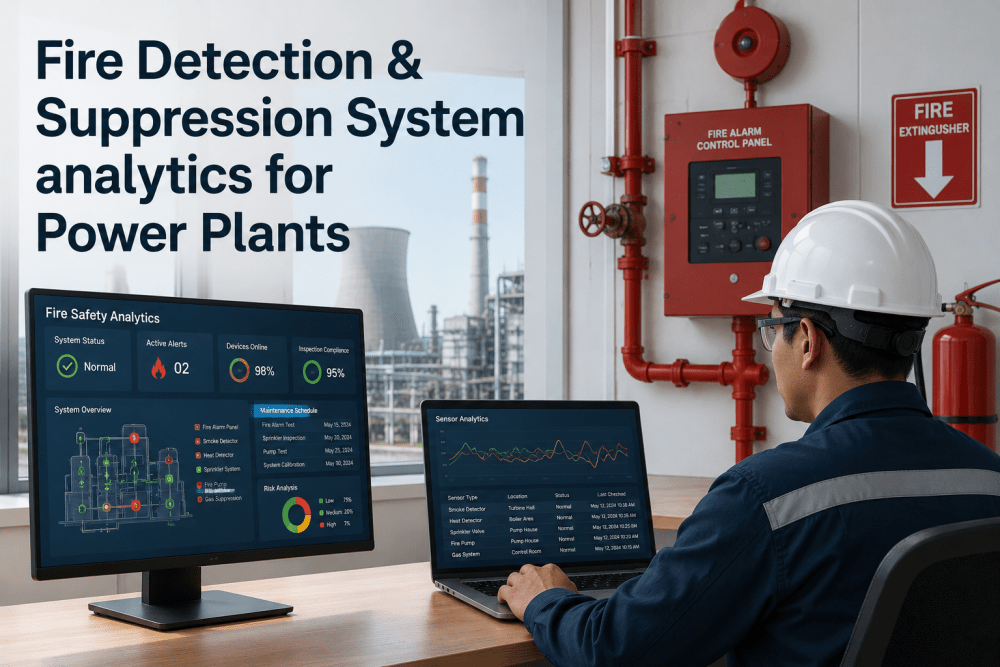
The iFactory compliance dashboard provides a real-time view of fire protection system readiness across the entire plant — showing the percentage of inspections completed on time, the number of open deficiencies by severity, the status of each deluge zone's last trip test, and the next scheduled test for every system. When an insurance surveyor, OSHA inspector, or fire marshal requests documentation, the system generates a comprehensive compliance report covering any time period with all inspection records, test results, deficiency logs, and corrective actions — formatted for the requesting authority and ready to submit without manual compilation.
Deficiency Tracking With Forced Resolution
Every fire protection deficiency identified during inspection or testing is tracked as a formal work order with a severity classification, a required resolution date based on NFPA 25 timelines, and an assigned owner. Critical deficiencies — a deluge valve that failed to open, a fire pump that failed to develop pressure — generate immediate notifications to plant management and cannot be closed without documented evidence of corrective action and successful re-test. Non-critical deficiencies are tracked on a standard resolution timeline with escalation if the deadline is missed. The system prevents deficiencies from being discovered, logged, and then forgotten — which is the most common reason that known fire protection gaps persist for months or years before a fire event exposes them.
Integration with Plant Operations and Work Management Systems
iFactory integrates with plant work management systems including SAP PM, IBM Maximo, and Infor EAM so that fire protection inspection tasks, corrective work orders, and compliance data flow seamlessly between the fire protection platform and the plant's primary maintenance management system. This integration eliminates the dual-entry problem where fire protection data is maintained in a separate system that is not visible to the maintenance planners who schedule outage work, and it ensures that fire protection system status is considered in every outage planning decision — preventing the situation where a deluge valve trip test is deferred because the outage scope did not include fire protection system testing.
Want to see your plant's fire protection compliance status in a single dashboard? Book a 30-minute platform walkthrough with the iFactory team.
Frequently Asked Questions
How often do deluge valves in a power plant need to be trip-tested?
NFPA 25 requires that deluge valves be trip-tested annually at a minimum. However, many power plants and their insurance carriers require quarterly or semi-annual trip testing for critical zones like the turbine lube oil area and the hydrogen generator enclosure because the consequences of a deluge valve failure in these zones are so severe. The trip test must flow water through all nozzles in the zone, verify flow pressure at the farthest nozzle, and confirm spray pattern coverage for every nozzle. A visual inspection of the valve in the open position without flowing water does not satisfy the trip test requirement because it does not verify that water can actually reach the nozzles at design pressure. To discuss the right trip test frequency for your plant's risk profile, book a demo and we will walk through the iFactory scheduling approach.
Can water-based suppression systems be used on hydrogen fires in generator enclosures?
Water spray is not the primary suppression agent for hydrogen fires because hydrogen flames burn at extremely high temperatures and water spray alone cannot cool the fuel source — hydrogen is a gas that continues to flow from the supply system as long as the leak persists. The standard approach for hydrogen generator enclosures is CO2 total flooding to displace oxygen and extinguish the flame, combined with automatic hydrogen supply isolation and inert gas purging to prevent re-ignition. Water spray may be used as a secondary cooling measure to protect surrounding equipment and structures from radiant heat, but it is not the primary suppression medium. The fire protection system design for hydrogen zones must be developed by a qualified fire protection engineer who understands the unique behavior of hydrogen fires and the interaction between suppression, ventilation, and hydrogen supply isolation. For guidance on hydrogen fire protection system design, contact the iFactory support team.
What is the most common reason fire protection systems fail during an actual fire event?
Post-fire incident investigations consistently identify three root causes that account for the majority of fire protection system failures. First, the deluge valve failed to open because it had not been trip-tested and internal corrosion or scale prevented operation — this is the single most common catastrophic failure. Second, detector lenses were obscured by dirt, oil, or dust, preventing the detection system from triggering — the detector showed normal status but could not see the fire. Third, a control valve was left in the closed position after maintenance and was not returned to open before the system was returned to service. All three of these failures are fully preventable through the NFPA 25 inspection and testing program described in this article, and all three are detectable through systematic inspection — but only if those inspections are actually performed, documented, and deficiencies are resolved within the required timelines.
How does iFactory handle fire protection inspections performed by outside contractors?
iFactory supports contractor-performed inspections through a role-based access model that gives contractors mobile access to the specific inspection checklists assigned to them while restricting access to plant-wide compliance data and configuration settings. When a contractor completes an inspection, the data flows directly into the same platform as in-house inspections — same format, same timestamp standards, same photo documentation requirements, same deficiency tracking workflow. The plant's fire protection coordinator can see all inspection activity from both in-house and contractor resources in a single view, with clear identification of which organization performed each task. This eliminates the common problem where contractor inspection reports arrive as PDFs or paper forms that must be manually transcribed into the plant's tracking system — a process that introduces delays, errors, and gaps in the compliance record.
What happens if we skip an annual deluge trip test during an outage because of schedule pressure?
Skipping a deluge trip test means operating the plant for up to 12 additional months without verifying that the most critical component in the fire protection system — the valve that delivers water to the fire zone — will actually open when needed. From a compliance perspective, a missed annual test is a direct NFPA 25 violation that will be cited by insurance surveyors and could result in coverage restrictions or premium increases. From a risk perspective, the probability of a deluge valve failure increases with every year it is not exercised, because corrosion, scale, and mechanical degradation are progressive conditions that do not reverse themselves. If a fire occurs in a zone where the deluge valve has not been trip-tested, the plant's liability exposure increases significantly because the failure to test will be identified in the post-incident investigation and used in any litigation or insurance claim dispute. iFactory's scheduling system is specifically designed to prevent this scenario by generating trip test tasks well in advance of outage dates and escalating alerts if the tasks are at risk of being deferred. To see how the scheduling and escalation system works, schedule a demo with our team.
Know Your Fire Protection Status Before the Insurance Surveyor Does
iFactory gives your safety and maintenance teams a single platform that tracks every fire protection component, schedules every inspection and test, captures results in the field, and generates compliance reports that satisfy insurance surveyors, fire marshals, and OSHA inspectors on demand. Stop discovering fire protection gaps during audits. Start managing them before they become incidents.