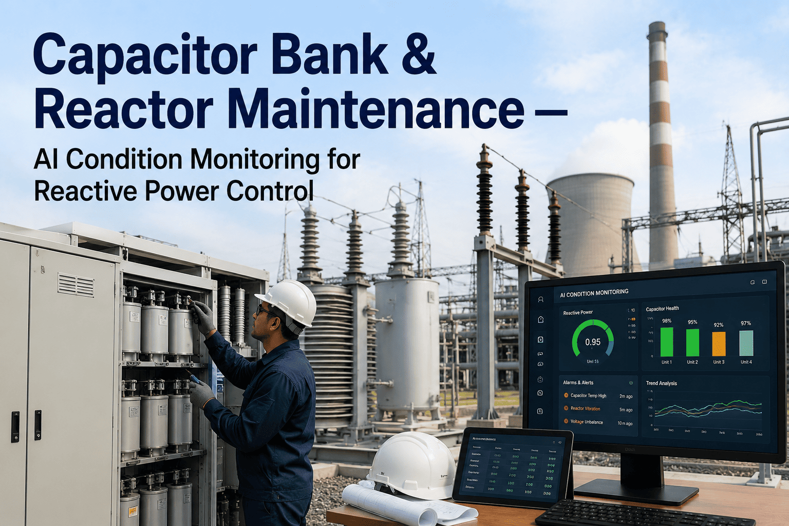
A capacitor bank rarely gives a long warning before it fails. Unlike a bearing that squeals for weeks or a valve that starts leaking gradually, a capacitor element under sustained overvoltage or harmonic stress can go from a normal reading on a Monday inspection to a ruptured case and a fire call within days. Reactors sitting in the same switchyard fail on a slower clock, with winding insulation degrading under thermal cycling and switching transients until a fault finally shows up during a routine energization. Maintenance managers running reactive power equipment are stuck watching case temperature, can pressure, fuse status, and winding condition across banks that sit energized for months between physical walkdowns, and the failure modes that matter most are exactly the ones that build quietly in that gap. iFactory's AI-driven platform keeps capacitor and reactor condition data flowing continuously, so a fuse imbalance or a winding hot spot gets caught before it turns into a switchyard trip. Book a demo to see reactive power asset monitoring configured for your substation.
AI-Driven · Reactive Power Assets · Substation Reliability
Capacitor Banks Fail Fast. Reactors Fail Quiet. Your Monitoring Needs to Catch Both.
iFactory tracks capacitor element condition, fuse status, and reactor winding health across your switchyard continuously, so drift gets caught while it is still a scheduled repair instead of an unplanned outage. Whether your fleet spans a single substation or dozens of banks across a transmission network, the same continuous view keeps every unit accounted for from one dashboard.
Days
The typical window between a capacitor bank passing inspection and a catastrophic case failure once overvoltage or overheating sets in
1 Phase
A single blown fuse on one phase of a three-phase bank can distort power factor correction and create current imbalance across the remaining elements
55°C
A common upper case temperature limit for industrial capacitor units, above which dielectric stress and failure risk climb sharply
100×
The making-current capacity typically specified for capacitor duty contactors relative to rated current, to survive inrush at energization
Asset Reference
What's Actually Sitting in a Capacitor Bank and Reactor Installation
Reactive power assets are a chain of individually simple components, and each one carries its own quiet way of drifting toward failure. Understanding where each component sits in the chain matters, because a symptom on one part of the installation often traces back to a completely different component upstream or downstream of it, and misreading that relationship is how a repair crew ends up replacing the wrong part.
01
Capacitor Units
Sealed elements filled with dielectric liquid or film, arranged in series and parallel sections to reach the bank's rated kVAR and voltage class.
02
Fuses and Switching Devices
Individual element fuses and capacitor-duty contactors or breakers that isolate a failed unit and handle the high inrush current at energization.
03
Series and Shunt Reactors
Inductive elements that limit inrush current, detune the system away from harmonic resonance, or absorb reactive power on lightly loaded lines.
04
Protection and Control
Relays, current and potential transformers, and automated switching controls that step banks in and out based on power factor and voltage targets.
How a Failure Builds
From a Single Weak Element to a Bank-Wide Trip
This is the pattern that plays out on nearly every reported capacitor bank failure, whether the underlying cause was overvoltage, harmonic distortion, moisture ingress, or simple age. Recognizing which stage a bank is sitting at is the difference between a technician swapping one unit during a lunch break and a crew scrambling to re-establish reactive power support after an unplanned trip.
1
Dielectric Stress Begins
Overvoltage, harmonic distortion, or sustained heat above the case rating starts breaking down one element's dielectric material ahead of its neighbors.
2
One Section Shorts Internally
A weakened element fails and shorts, and the remaining series sections in that unit now carry higher voltage and draw more current than before.
3
Fuse Blows, Bank Runs Unbalanced
The element fuse clears the fault, but the bank keeps running with one phase or section out of service, quietly hurting the power factor it was installed to fix.
4
Remaining Units Take the Extra Load
Neighboring capacitor units absorb the redistributed current and voltage stress, accelerating their own aging on a compressed timeline.
5
Case Rupture or Bank Trip
Without intervention, the next weak point fails violently enough to rupture a case or trip protection for the whole bank, taking reactive power support offline.
Fault Reference
Common Symptoms Across Capacitor Banks and Reactors
Most reactive power equipment problems announce themselves through one of a handful of recurring symptoms. Matching the symptom to its likely cause quickly is what keeps a routine finding from turning into extended equipment downtime while a crew works through possibilities one at a time.
| Symptom |
Likely Cause |
Typical Response |
| Elevated Case Temperature |
Dielectric stress, poor ventilation, or harmonic loading above design rating |
Verify ventilation and loading, schedule infrared inspection of the affected unit |
| Blown Element Fuse |
Internal dielectric breakdown in one series section |
Isolate and test the affected unit, check remaining phases for imbalance |
| Frequent Switching Cycles |
Unstable load profile or automated controller tuned too aggressively |
Review controller deadband settings and switching sequence logic |
| Reactor Winding Hot Spot |
Insulation degradation or cooling system restriction |
Schedule thermal imaging and insulation resistance testing on the reactor |
| Rising Harmonic Distortion |
Nonlinear loads interacting with an undertuned or aging filter reactor |
Run a power quality scan and confirm detuning factor against current load mix |
How the Platform Works
From Switchyard Instrumentation to a Scheduled Repair
Most substations already have the sensors needed to see these trends coming; what has been missing is a system that pulls that data together, compares it against the right baseline, and surfaces it before a hard alarm fires. Here is how that gap gets closed.
1
Continuous Condition Pull
Case temperature, fuse status, current imbalance, and reactor winding temperature are pulled from existing protection and SCADA instrumentation continuously.
2
Per-Unit Baseline Modeling
Every capacitor unit and reactor is modeled against its own healthy baseline, so a slow rise in case temperature or a widening current imbalance is caught as a trend.
3
Harmonic and Switching Pattern Analysis
Switching frequency and harmonic distortion are tracked together, so a controller cycling too often or a reactor drifting off its detuning point gets flagged as a pattern rather than a single alarm.
4
Maintenance Alert Before Escalation
Maintenance teams see the flagged unit and likely cause while there is still time to schedule an isolated repair instead of reacting to a bank-wide trip.
Planned vs. Unplanned
The Real Cost Difference Between a Scheduled Swap and an Emergency Isolation
Planned Repair
A single unit is isolated during a planned maintenance window without touching the rest of the bank
A replacement element is ordered ahead of time based on the flagged trend, not sourced under time pressure
The rest of the bank keeps supporting power factor correction while the one unit is swapped
Root cause, whether overvoltage, harmonic loading, or ventilation, can be investigated calmly and addressed at the source
Unplanned Failure
A case rupture or bank trip takes the full unit offline without warning, often during peak reactive power demand
Emergency sourcing and expedited freight replace a routine parts order, at a much higher cost
Power factor correction is lost site-wide until the bank is restored, risking utility penalty charges on the bill
Root cause investigation happens after the fact, often without the data needed to confirm what actually triggered it
A Blown Fuse on One Phase Shouldn't Take Six Weeks to Notice.
Continuous case temperature, fuse status, current imbalance, and reactor winding monitoring across every bank in your switchyard, configured for your protection scheme.
Readiness Check
Six Questions to Ask About Your Reactive Power Monitoring Today
1
Is case temperature on every capacitor unit trended continuously, not just checked during scheduled infrared surveys
2
Would a blown element fuse on one phase surface as an alert, or only get discovered at the next physical walkdown
3
Is switching frequency on automated banks monitored for drift away from design duty cycle
4
Are reactor winding temperatures trended against a healthy baseline rather than a single fixed alarm threshold
5
Is harmonic distortion tracked continuously enough to catch a detuning drift before it causes resonance
6
Can your team see the condition of every bank across the site from one view instead of separate local panels
From the Field
What a Substation Team Learned From One Bank That Almost Went Up in Smoke
We had a capacitor bank that passed a visual inspection on a Friday, and by the following Wednesday one unit had a ruptured case. Looking back at the data afterward, the case temperature on that specific unit had been climbing for close to two weeks, well ahead of anything our alarm thresholds would have caught, because the alarm was set for an absolute value, not a trend against that unit's own baseline. Nobody was ignoring anything, the rise just never crossed a fixed line until it was already too late to plan around it. Once we had every unit trending against its own history instead of one shared threshold, we caught a second bank heating up the same way almost three weeks before it would have reached the same point, and that time we swapped the unit during a planned weekend outage instead of an emergency one.
— Maintenance Manager, Regional Transmission Substation
Conclusion
Reactive Power Equipment Doesn't Get a Second Chance to Warn You
Capacitor banks fail fast once dielectric stress sets in, and reactors fail quietly enough that a winding problem can sit undetected for months. Both patterns point to the same gap: fixed alarm thresholds and periodic walkdowns catch problems only after they have already become urgent.
iFactory's AI-driven platform trends every capacitor unit and reactor against its own healthy baseline continuously, so a maintenance team sees the drift while there is still a scheduled repair window available instead of an emergency isolation. That baseline approach matters specifically because fixed alarm thresholds are set to catch a value that is already dangerous, while a trend against a unit's own history can catch the same problem while it is still several weeks away from that point.
For sites running mixed fleets of older and newer capacitor technology, that per-unit baseline also removes the guesswork of comparing dissimilar equipment against a single shared threshold, since a unit installed a decade ago and one installed last year rarely share the same healthy operating signature to begin with.
Across a substation with dozens of banks, that same continuous view rolls up into a single priority list, so a maintenance manager can see exactly which unit needs attention next without reconstructing the picture from separate local panels. Book a demo to see it configured for your switchyard.
Frequently Asked Questions
Capacitor Bank and Reactor Monitoring — What Maintenance Managers Ask
Why do capacitor banks fail so much faster than most other electrical equipment once a problem starts?
A capacitor unit's dielectric material breaks down under sustained overvoltage, harmonic stress, or heat in a way that tends to accelerate once it starts, rather than progressing at a steady, predictable rate the way mechanical wear usually does. Once one series section inside a unit fails and shorts, the remaining sections in that same unit absorb higher voltage and current, which speeds up the failure of the next weak point rather than slowing it down. That compounding effect is why a bank that looked fine at a scheduled inspection can reach a ruptured case within days rather than the months of warning a bearing or a pump seal typically provides. It is also why relying on a monthly or quarterly walkdown schedule, however diligent the inspector, still leaves a window wide enough for the entire failure sequence to complete unseen.
Book a demo to see how continuous trending catches that curve early.
How does a single blown fuse on one phase actually affect power factor correction?
When one phase or section of a capacitor bank drops out due to a blown fuse, the bank no longer delivers its full rated reactive power support, and the current across the remaining phases becomes unbalanced. That imbalance can, in some configurations, make the power factor correction problem worse rather than simply reducing it proportionally, since an unbalanced bank interacts differently with the load than a fully healthy one would. Left unaddressed, this also puts additional stress on the surviving units, which is how a single fuse event on a bank that keeps running quietly turns into a second and third failure over the following weeks. Facilities billed on power factor penalties can see that cost show up on a utility statement well before anyone traces it back to a single blown element sitting unnoticed inside an otherwise energized bank.
Can this monitor reactors and capacitor banks together, or do they need separate systems?
Yes. Capacitor units and reactors are modeled against their own individual baselines within the same platform, so temperature, current, switching frequency, and harmonic data from both asset types feed into one shared view rather than requiring separate monitoring systems. This matters because reactors and capacitor banks are frequently installed together in detuned filter configurations, and a drift in one often has a direct relationship to the condition of the other.
Contact support to discuss connecting your specific switchyard configuration.
Does continuous monitoring replace infrared and ultrasound inspection rounds?
No. Physical infrared and ultrasound inspections still catch things that instrumentation trends alone cannot, such as loose connections at fuseholders, external corrosion, or arcing sounds that a maintenance technician can hear but a sensor was never placed to detect. What continuous monitoring changes is how that inspection time gets used, since a team walking in already knowing which unit has a rising temperature trend can focus their infrared camera and their attention exactly where it is needed rather than scanning an entire bank evenly every time. Most teams find their physical rounds become more targeted and more valuable once trend data narrows down where to look first.
What instrumentation does a capacitor bank or reactor installation need before this kind of monitoring can start?
Most capacitor banks and reactors already have current transformers, potential transformers, and protection relays in place as part of their standard switchgear and control scheme, and this existing instrumentation is typically sufficient to begin generating trend data. In most cases the platform connects to that existing protection and SCADA data rather than requiring a new sensor package to be installed on the switchyard equipment itself, which means a typical site can start seeing trend visibility within the early weeks of connection.
Catch the Weak Element Before It Takes the Whole Bank Down.
Continuous capacitor unit, fuse, reactor, and harmonic monitoring across your switchyard, configured for your specific reactive power scheme.