Steam turbine governor valves and control valves are the final control elements that translate the electronic speed and load signal from the governor system into mechanical steam flow adjustment, and their response time, linearity, and seating integrity directly determine whether the turbine can maintain stable operation during load changes, grid frequency disturbances, and emergency trip events. A governor valve that has developed stiction in its stem packing will not respond smoothly to small load adjustments, causing load oscillations that can trigger protective relay actions. A control valve with seat leakage will pass steam when commanded closed, preventing the turbine from reaching true minimum load and creating thermal stress in the downstream stages. A stop valve that fails to close within its specified stroke time during a trip event exposes the turbine to overspeed risk, which is the most catastrophic failure mode in steam turbine service. Facilities that treat valve maintenance as a periodic overhaul activity rather than a condition-monitored program are unable to detect the gradual degradation in valve response that precedes most valve-related operational problems. Teams that want to build a structured valve maintenance program can Book a Demo to see how iFactory tracks valve stroke times, seat leakage trends, and servo actuator performance from one outage cycle to the next.
A Sticky Governor Valve Costs More Than a Rebuild. It Costs a Trip.
iFactory tracks stroke times, seat leakage, and servo response for every valve in your turbine steam path, so degradation is caught before it causes load oscillations or trip failures.
Four Valve Types That Control Every Aspect of Turbine Steam Flow
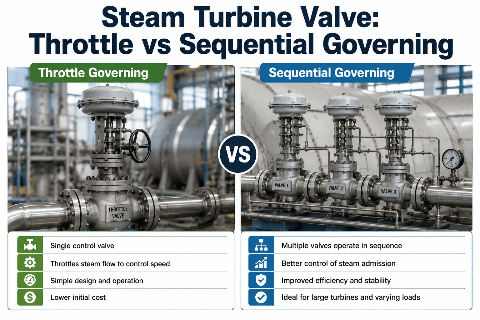
The steam path through a turbine is controlled by four distinct valve types, each serving a different function in the safety and load control hierarchy. The stop valve is the ultimate safety device that must close completely and rapidly when the overspeed protection system actuates. The governor valve modulates steam flow to control turbine speed during startup and load during normal operation. The control valve provides fine load adjustment and is often arranged in a sequential opening pattern to optimize part-load efficiency. The reheat stop and intercept valves protect the turbine from overspeed caused by steam stored in the reheater and hot reheat piping. The visual below shows each valve in its position within the steam path, along with the critical performance parameter that defines its maintenance priority.
Must close fully against full steam pressure with zero leakage when seated. The trip-and-throttle valve combination requires both rapid closure and tight shutoff. Stroke time testing during every outage is non-negotiable because this valve is the primary overspeed protection barrier.
Modulates steam flow in response to the governor output signal. Must move smoothly through its entire stroke range without stiction, deadband, or hysteresis that would cause load swings or speed oscillations. Multiple governor valves often open sequentially, and the crossover point between valves must be calibrated correctly.
Provides precise steam flow adjustment for small load changes. In multi-valve arrangements, control valves handle the fine trimming after governor valves have set the approximate load level. Seat leakage in control valves prevents the turbine from reaching true minimum load and causes thermal cycling in the low-pressure stages.
Closes rapidly during a trip to prevent the stored energy in the reheater and hot reheat piping from accelerating the turbine intermediate and low-pressure sections to overspeed. The reheat stop valve works in conjunction with the intercept valve, and both must meet their stroke time requirements independently.
Valve Stroke Testing: Measuring Response Time From Signal to Full Travel
Valve stroke testing is the most direct measurement of valve mechanical health available without disassembling the valve. It measures the time required for the valve to move from its current position to a commanded position, typically from fully open to fully closed for stop valves and across the full stroke range for governor and control valves. The test is performed by injecting a step change command into the servo or solenoid valve and recording the valve stem position versus time using a position transducer. The resulting stroke-time profile reveals mechanical problems that are invisible during normal operation, including packing friction, hydraulic delays in the actuator, mechanical binding in the guide, and degradation in the servo valve response. The four stroke parameters below are the minimum set that must be measured and recorded for each valve during every stroke test.
Dead Time
Target: under 0.05 secondsThe elapsed time between the command signal and the first detectable movement of the valve stem. Dead time is caused by hydraulic transmission delay in the servo system, clearance in the mechanical linkage, and slack in the actuator-to-stem connection. Increasing dead time indicates air in the hydraulic fluid, worn linkage bushings, or degradation in the servo valve pilot stage. Dead time has no acceptable threshold for stop valves because any delay in the initiation of closure during a trip reduces the overspeed margin.
Full Stroke Time
Target: varies by valve typeThe total time from command to the valve reaching its final position. For main stop valves, the typical requirement is 0.15 to 0.30 seconds from trip signal to fully closed. For reheat intercept valves, the requirement is typically 0.3 to 0.5 seconds. Governor and control valves have less stringent stroke time requirements because they are modulating valves, but their full stroke time should still be consistent with the original commissioning data. A stroke time that has increased by more than 20% from the baseline indicates significant mechanical degradation.
Stroke Linearity
Target: within 2% of commandThe relationship between the commanded position and the actual stem position at intermediate points during the stroke. A linear valve moves proportionally to the command signal at all points in its travel. Non-linearity appears as the valve moving faster in some portions of the stroke and slower in others, caused by uneven packing friction, worn guides, or distorted valve stems. Linearity is critical for governor and control valves because the governor algorithm assumes a linear relationship between valve position and steam flow. Non-linearity causes the governor to hunt for the correct position, producing load oscillations.
Hysteresis
Target: under 1% of strokeThe difference in stem position when approaching the same command point from opposite directions. Measured by stroking the valve from open to closed and then from closed to open, recording the position at each command level. Hysteresis is caused by static friction in the packing and guides that must be overcome to initiate movement in each direction. High hysteresis means the valve position at any given command is uncertain by the hysteresis amount, which directly translates into load uncertainty. Governor valves with hysteresis above 1% will cause noticeable load oscillation during frequency response mode.
Seat Leakage Classification and Acceptance Criteria for Turbine Valves
Seat leakage is the flow of steam past the valve seat when the valve is commanded fully closed. For stop valves, any measurable seat leakage is a concern because it means the overspeed protection barrier is compromised. For governor and control valves, seat leakage prevents the turbine from reaching minimum load, wastes steam, and creates thermal stress in downstream components. Seat leakage is quantified by pressurizing the valve body upstream of the seat and measuring the flow rate that passes through the closed valve. The results are classified according to industry standards, with the most stringent requirements applied to stop valves and progressively less stringent requirements for modulating valves. The table below shows the typical leakage classes applied to steam turbine valves and the maximum allowable leakage rate for each class.
| Leakage Class | Max Leakage Rate | Typical Application | Test Method |
|---|---|---|---|
| Class I | No measurable leakage | Main stop valves, reheat stop valves | Pressure decay or bubble test at operating pressure differential |
| Class II | 0.1% of rated capacity coefficient | Governor valves at minimum load condition | Water or air test at rated pressure differential per ANSI/FCI 70-2 |
| Class III | 0.01% of rated capacity coefficient | Control valves requiring tight shutoff | Water or air test per ANSI/FCI 70-2 with precision flow measurement |
| Class IV | 0.01% of rated capacity coefficient | General service control valves | Standard leakage test per ANSI/FCI 70-2 at max differential pressure |
| Class V | 5 x 10^-4 ml per minute per inch of seat diameter per psi differential | Valves requiring metal-to-metal seat tightness | High-precision gas test with mass flow measurement |
| Class VI | 0.5 ml per minute per inch of seat diameter at 50 psi air | Soft-seated valves, not typical for main steam service | Air bubble test per ANSI/FCI 70-2 at 50 psig or operating differential |
When a stop valve fails its Class I leakage test, the root cause is almost always physical damage to the seating surfaces. In high-pressure main steam service, the valve seat and disc are subjected to erosion from high-velocity steam during throttling, wire-drawing damage from partial closure at high differential pressure, and galling from the mechanical impact of rapid closure during trip events. The repair options range from lapping the seating surfaces to restore a line contact, which is the standard maintenance approach, to replacing the seat and disc if the damage has progressed beyond what lapping can correct. The critical decision is determining whether the leakage is from seating surface damage, which is repairable, or from stem distortion or misalignment, which will cause the leakage to recur immediately after lapping. Tracking leakage test results across multiple outage cycles reveals whether the leakage is stable, gradually increasing, or rapidly accelerating, which directly informs the repair-versus-replace decision. iFactory stores every leakage test result with the valve identity, outage date, and test conditions, so your team can see the degradation trajectory at a glance. Book a Demo to see how iFactory builds valve leakage histories that drive maintenance decisions.
Servo Actuator Degradation: What Fails Inside the Hydraulic Control System
The servo actuator is the electromechanical device that converts the governor electronic output signal into the hydraulic force that moves the valve stem. It consists of a servo valve, a hydraulic cylinder, a position feedback transducer, and the associated hydraulic supply and return piping. Degradation in any component of this system affects the valve's ability to respond accurately and quickly to governor commands. The four failure modes below represent the most common causes of servo actuator degradation in steam turbine service, each producing a distinct signature in the valve stroke test data that can be detected before the degradation causes an operational problem.
Servo Valve Spool Sticking
Stroke Signature: Intermittent deadband, erratic response at small commandsThe servo valve spool is a precision-machined component that meters hydraulic fluid to the actuator cylinder in proportion to the electrical command signal. When contamination in the hydraulic fluid lodges between the spool and the bore, the spool sticks at small signal levels, creating a deadband where small command changes produce no valve movement. As the command increases, the spool breaks free suddenly, causing the valve to overshoot the commanded position. This produces the classic stiction behavior visible in stroke test data as a flat response region near zero command followed by a jump. The root cause is hydraulic fluid contamination, and the fix is servo valve overhaul and fluid filtration upgrade. Left uncorrected, spool sticking causes load oscillations that worsen as contamination accumulates.
Hydraulic Cylinder Seal Wear
Stroke Signature: Slower stroke, drift at null, increased hydraulic demandThe piston and rod seals in the hydraulic cylinder prevent fluid bypass from the pressure side to the return side. As these seals wear, internal leakage increases, which means the actuator cannot develop full force at the rated hydraulic pressure. The visible effect in stroke test data is a gradual increase in full stroke time as more of the hydraulic flow bypasses the piston instead of moving it. In severe cases, the valve will drift from its commanded position when the servo valve is at null, because the internal leakage creates an unbalanced force on the piston. Seal wear is a normal aging mechanism that can be predicted from the trend in stroke time over multiple outage cycles, allowing seal replacement to be scheduled before the stroke time exceeds the acceptance limit.
Position Feedback Drift
Stroke Signature: Offset between command and position, no change in mechanical responseThe LVDT or rotary position transducer provides the valve stem position signal back to the governor. When this transducer drifts or loses calibration, the governor receives incorrect position feedback and drives the valve to a position that compensates for the error, resulting in the valve being at a different actual position than the governor believes. In stroke test data, this appears as a constant offset between the command signal and the measured position, even though the mechanical response of the valve may be perfectly normal. The danger is that the governor's control algorithm is operating on incorrect position data, which can cause load errors, improper valve sequencing in multi-valve arrangements, and incorrect stroke time calculations if the position signal is used for timing. Transducer calibration must be verified at every outage.
Hydraulic Supply Pressure Decay
Stroke Signature: All valves on the system show simultaneous slowingWhen the hydraulic supply pressure drops below the design value, all valves served by that hydraulic system show increased stroke times simultaneously. This distinguishes supply pressure decay from individual actuator problems, which affect only one valve. Supply pressure decay is caused by wear in the hydraulic pump, relief valve drift, accumulated internal leakage from multiple actuators exceeding the pump capacity, or partial blockage in the supply filter. The diagnostic approach is to measure the supply pressure at the actuator during a stroke test and compare it to the design pressure. If the pressure drops significantly during valve movement, the supply system cannot maintain flow under load and must be investigated independently of the valve mechanics.
Valve Degradation Is Measurable Years Before It Causes a Trip.
iFactory stores every stroke test, leakage measurement, and servo diagnostic in a timeline for each valve, so your team sees the degradation trend and schedules maintenance before the valve fails on demand.
Which Failure Mode Affects Which Valve Type and What It Does to Turbine Operation
Not all failure modes affect all valve types equally. A failure mode that is catastrophic for a stop valve may be merely an annoyance for a control valve, and vice versa. The matrix below maps the seven most common valve failure modes against the four valve types, rating the operational severity of each combination from Low to Critical. This matrix serves two purposes during maintenance planning: it identifies which failure modes to prioritize for each valve type during inspection, and it explains to operations personnel why a specific valve finding, such as packing leakage on a governor valve, has a different operational urgency than the same finding on a stop valve.
| Failure Mode | Stop Valve | Governor Valve | Control Valve | Intercept Valve |
|---|---|---|---|---|
| Seat Leakage | Critical | High | Medium | Critical |
| Slow Stroke Time | Critical | Medium | Low | Critical |
| Stiction / Deadband | Low | Critical | High | Low |
| Packing Leakage | Medium | High | Medium | Medium |
| Stem Binding | Critical | High | Medium | Critical |
| Servo Drift | Low | High | High | Low |
| Disc Erosion | High | High | Medium | High |
The matrix makes it immediately clear that stop valves and intercept valves are most vulnerable to failures that affect their ability to close rapidly and completely, which is their primary safety function. Governor valves are most vulnerable to failures that affect their modulation accuracy, because their primary function is precise steam flow control. Control valves occupy an intermediate position where most failure modes are significant but not immediately safety-critical. This differentiation is essential for maintenance prioritization. During a limited-outage window where not all valves can be fully overhauled, the matrix directs the maintenance effort toward the failure modes that pose the highest operational risk for each valve type, rather than applying a uniform inspection scope to all valves regardless of their function.
Condition-Based Maintenance Intervals for Turbine Valve Systems
Turbine valve maintenance has traditionally been performed on fixed time intervals, typically during every major overhaul regardless of valve condition. This approach is wasteful for valves that are in good condition and dangerous for valves that degrade between overhauls due to operating conditions that were not anticipated in the original interval calculation. A condition-based approach uses the actual performance data from stroke testing, leakage testing, and operational monitoring to determine when each valve needs maintenance, allowing the interval to be extended for healthy valves and shortened for degrading valves. The framework below defines four maintenance actions, each triggered by specific condition indicators rather than calendar time.
When the previous stroke test showed all parameters within acceptance limits and no operational complaints have been recorded since the last test, the maintenance action is limited to performing a repeat stroke test and recording the results. No disassembly, no packing replacement, no servo valve removal. The purpose is to establish the next data point in the trend and confirm that the valve is still healthy. This is the minimum maintenance action and should be the default for valves that have demonstrated stable performance over multiple consecutive outage cycles. The cost is limited to the labor and instrumentation for the stroke test itself, typically two to four hours per valve.
When the stroke test shows a measurable increase in stroke time or hysteresis that is within the acceptance limit but trending worse, or when operations reports minor steam leakage at the packing gland, the maintenance action includes servo valve removal and bench testing, packing replacement, and repeat stroke testing after reassembly. The valve body is not opened and the seat is not inspected. This action addresses the most common degradation modes, which are servo contamination and packing wear, without the cost and schedule impact of a full valve disassembly. The typical duration is eight to sixteen hours per valve depending on servo valve complexity.
When the stroke test or leakage test indicates a significant performance shortfall, or when a valve has been involved in an operational event such as a failed trip or load rejection, the valve is fully disassembled for internal inspection. This includes removal of the disc and seat for visual and dimensional inspection, guide bore measurement, stem straightness verification, and seat lapping or replacement as required. The servo system is serviced at the same time. This is a major maintenance action that requires 24 to 48 hours per valve and must be included in the outage schedule as a critical path item. The inspection findings are documented and compared to the previous inspection to quantify the rate of internal degradation.
When the full inspection reveals damage that cannot be corrected by in-situ maintenance, the valve must be removed and either rebuilt in a qualified shop or replaced with a new or refurbished unit. This is the most expensive and time-consuming maintenance action, often requiring 48 to 96 hours of outage time including rigging, removal, reinstallation, and full recommissioning testing. The decision to rebuild versus replace depends on the availability of replacement units, the lead time for shop rebuild, the severity of the damage, and whether the original valve design has known deficiencies that a replacement unit would address. This decision is significantly easier to make when the historical performance data shows a clear degradation trajectory that justifies the investment.
What Operators See When Turbine Valves Start Degrading
Long before a valve fails a formal stroke test, it produces observable symptoms during normal operation that operators can recognize and report if they know what to look for. These symptoms are the early warning system that triggers condition-based maintenance before the degradation reaches the point where it would cause a trip or force an emergency outage. The six operational symptoms below are arranged from the earliest and most subtle to the latest and most severe, with the likely valve cause for each symptom. Training operators to recognize these symptoms and report them with sufficient detail for the maintenance team to correlate with valve performance data is one of the highest-value investments a turbine owner can make in reliability improvement.
Small Load Oscillations During Steady State
Most likely: Governor valve stiction or servo deadbandThe load reading fluctuates by 1 to 3 MW around the setpoint even though no external load change has been requested. The oscillation may be too small to trigger an alarm but is visible on the trend recorder. This is the earliest detectable symptom of governor valve degradation and indicates that the valve is sticking at small signal levels. The governor is constantly making small corrections that overcorrect due to the deadband, producing a limit cycle oscillation. At this stage, the valve will still pass a stroke test because the stiction only manifests at very small command changes that may not be included in the standard test profile.
Inability to Hold Precise Load Setpoint
Most likely: Control valve hysteresis or governor valve non-linearityThe turbine load stabilizes but not at the requested setpoint, with a persistent offset of 3 to 5 MW that the governor cannot eliminate. This indicates that the valve position feedback or the valve's actual flow characteristic no longer matches what the governor algorithm expects. Hysteresis in the control valve means the same command produces different positions depending on the direction of approach, creating a position uncertainty that the governor cannot resolve. The governor settles at a position where the error is within the deadband but not at zero error, leaving a persistent load offset.
Load Swing During Automatic Frequency Response
Most likely: Governor valve stroke time degradation or servo response lagWhen the unit is in automatic frequency control mode and the grid frequency changes, the turbine load response is slower than expected or overshoots the required load change. The governor is commanding the valve to move, but the valve is not responding fast enough or is overshooting due to degraded servo response. This symptom is significant because it means the turbine is not fulfilling its grid support obligation, which can result in regulatory penalties and reduces the unit's value in the ancillary services market. The degradation is typically in the 15 to 25% stroke time increase range by the time it becomes noticeable in frequency response performance.
Steam Leakage at Valve Bonnet During Operation
Most likely: Packing degradation, stem erosion, or packing gland misadjustmentVisible or audible steam leakage from the valve packing gland during operation. Minor packing leakage is a normal condition that is managed by adjusting the packing gland follower, but increasing leakage that cannot be controlled by gland adjustment indicates that the packing rings have degraded to the point where replacement is required. If the leakage is accompanied by steam cutting of the stem surface, the stem itself is being damaged and must be inspected for dimensional loss when the valve is disassembled. Uncontrolled packing leakage on a governor valve is more urgent than on a stop valve because the governor valve moves continuously and the packing is subjected to more thermal cycling.
Minimum Load Higher Than Normal
Most likely: Governor or control valve seat leakageThe turbine cannot be loaded below a certain minimum even with all governor and control valves commanded fully closed. This indicates that one or more valves are passing steam through the seat when closed, effectively adding a fixed amount of steam flow that the governor cannot eliminate. The minimum load increase corresponds directly to the amount of leakage flow. A 5 MW increase in minimum load from a design minimum of 30 MW represents a 17% increase that affects the unit's ability to remain synchronized during low-demand periods and may force a shutdown that could have been avoided with timely valve maintenance.
Abnormal Vibration During Valve Throttling
Most likely: Disc instability, seat damage, or high-pressure drop across partially open valveThe turbine or the valve body itself experiences increased vibration when the valve is in the throttling range, typically 15 to 40% open. This indicates that the flow pattern through the valve has become unstable, which can be caused by damage to the valve disc profile, erosion of the seat that changes the flow area geometry, or operation at a pressure drop that exceeds the valve's stable throttling range. Valve-induced vibration can cause fatigue damage to the valve stem, connection linkage, and adjacent piping, and it represents an immediate maintenance requirement because the vibration will accelerate any existing damage to the valve internals. This symptom should trigger removal of the valve for inspection at the earliest opportunity regardless of the outage schedule.
Turbine Governor and Control Valve Maintenance — Common Questions
How often should steam turbine governor valves be stroke tested?
Governor valves should be stroke tested during every scheduled outage, which for most units means annually or semi-annually depending on the outage cycle. Stop valves and intercept valves must be stroke tested at every outage without exception because their stroke time directly affects overspeed protection. Governor and control valves should also be stroke tested whenever operational symptoms suggest degradation, such as load oscillations or frequency response problems, even if an outage is not otherwise planned. Some facilities have installed online stroke testing systems that can test governor valves during operation by injecting small command perturbations and measuring the response without moving the valve through its full range. These systems enable continuous monitoring of valve response between outages and can detect stiction and deadband development months before it would be found during a scheduled outage test. Book a Demo to see how iFactory integrates online and outage stroke test data into a single valve health timeline.
What is the acceptable stroke time for a main steam stop valve and how is it measured?
The acceptable stroke time for a main steam stop valve is specified by the turbine manufacturer and typically ranges from 0.15 to 0.30 seconds from the trip signal to fully closed position, though some older units may have higher allowable values up to 0.5 seconds. The measurement is performed by installing a position transducer on the valve stem, initiating a trip signal from the overspeed protection system, and recording the stem position at a minimum sampling rate of 1000 samples per second to capture the rapid closure accurately. The test must be performed with the valve under normal operating pressure because hydraulic system performance and steam flow forces on the disc affect the closure time. Testing at reduced pressure or with the turbine offline will produce a faster stroke time that does not represent the valve's true trip response. The test should be repeated a minimum of three times and the slowest result used as the reported stroke time, because the first trip after a long standstill may be slower due to static friction that does not represent the in-service condition. The iFactory Support team can advise on configuring stroke test data capture to meet manufacturer and insurance requirements.
Can valve packing be replaced without removing the valve from the turbine?
Yes, on most turbine designs the valve packing can be replaced in-situ by removing the packing gland follower and extracting the packing rings through the bonnet opening without removing the valve body from the piping. This is a standard maintenance activity that can typically be completed in four to eight hours per valve depending on the packing arrangement and accessibility. However, in-situ packing replacement has limitations. It cannot address stem damage that has occurred from packing leakage, it cannot correct gland misalignment that may have caused uneven packing wear, and it does not provide access to inspect the seat and disc. If the stem shows visible scoring or erosion from steam cutting at the packing location, the valve must be removed for stem inspection and possible replacement regardless of whether the packing alone could be replaced in-situ. The decision between in-situ packing service and full valve removal should be based on the combined assessment of packing condition, stem condition observed at the accessible portion, and the stroke test results that indicate whether internal degradation is also present.
What causes governor valve stiction and can it be fixed without a major overhaul?
Governor valve stiction is caused by excessive static friction in the packing gland, in the valve stem guide bushings, or in the servo valve spool. The most common cause is packing that has been over-compressed to control leakage, which increases the radial pressure on the stem and creates friction that exceeds the force available from the servo actuator at small signal levels. The first corrective action is to relieve the packing gland compression to the minimum required to control leakage, which often resolves mild stiction without any disassembly. If the stiction persists after packing adjustment, the packing material may have degraded and lost its lubricity, requiring packing replacement. If stiction persists after packing replacement, the stem guide bushings may be worn or corroded, which requires valve disassembly to inspect and repair. Servo valve stiction, which produces similar operational symptoms, is corrected by servo valve removal and bench testing or overhaul. The key is to diagnose whether the stiction is in the valve mechanism or the servo system before committing to a maintenance scope, which requires comparing the stroke test profile against the known signatures for each failure mode. Book a Demo to see how iFactory uses stroke profile analysis to pinpoint the stiction source.
How does seat leakage in a governor valve affect turbine efficiency and what is the financial impact?
Seat leakage in a governor valve allows steam to pass through the valve when it is commanded closed, which means the turbine receives more steam flow than the governor intends at any given load point. The immediate effect is that the minimum achievable load increases because the leaked steam produces power that cannot be eliminated by closing the valve further. The efficiency impact occurs because the leaked steam enters the turbine at the first stage pressure rather than being throttled through the valve, which bypasses the throttle loss calculation in the heat balance and produces a small amount of additional power at a very high incremental heat rate. For a unit that frequently operates at low load during off-peak hours, the inability to reach true minimum load can force a shutdown and restart cycle that costs far more than the valve repair. A 5 MW increase in minimum load on a 300 MW unit that operates 2000 hours per year at minimum load represents 10,000 MWh of unwanted generation that may need to be curtailed through other means. The financial impact depends on the unit's operating pattern, but for most units the cost of ignoring governor valve seat leakage exceeds the cost of the repair within one to two operating seasons.
Your Stop Valves Have One Chance to Close Correctly. Make Sure They Are Ready.
Talk to iFactory about building a turbine valve maintenance program where every stroke test, leakage result, and servo diagnostic is tracked per valve and trended across outage cycles to drive condition-based maintenance decisions.