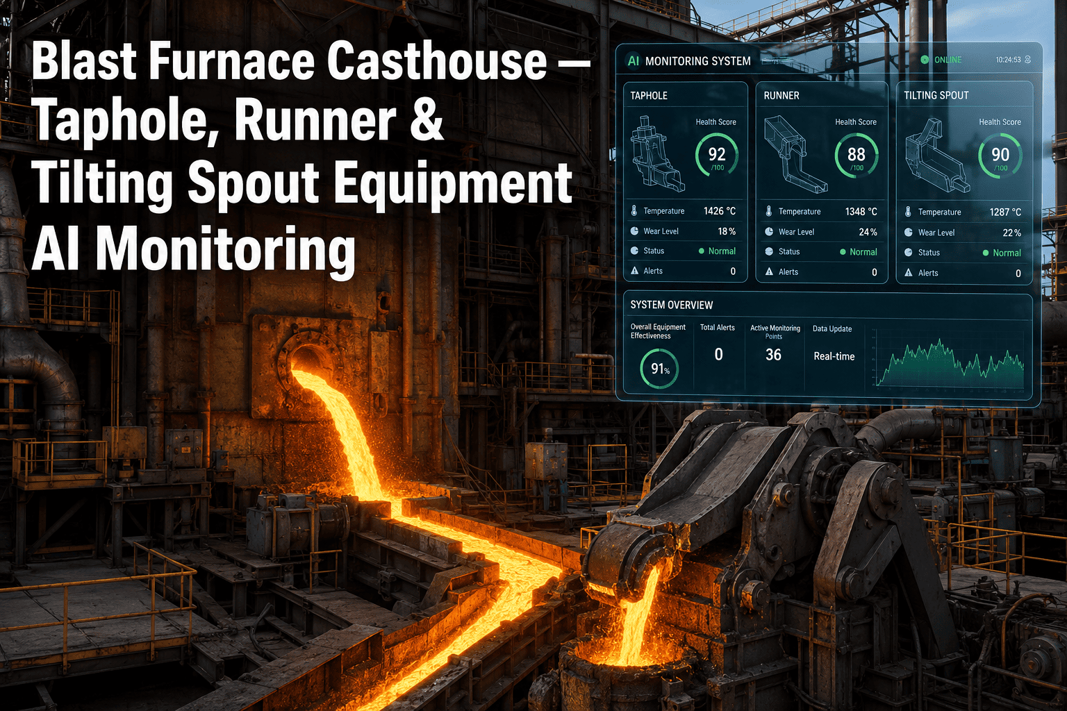
Every blast furnace campaign lives or dies a little on the cast house floor, where a taphole drilled a few degrees off angle, a runner with unnoticed refractory erosion, or a torpedo car filled past its safe margin turns a routine tap into a delay, a spillage incident, or a refractory replacement nobody had scheduled. Cast house operations — taphole drilling and plugging, runner and skimmer condition, and torpedo car or ladle filling — get treated as manual, experience-driven work at most plants, which means consistency depends entirely on which crew is on shift. iFactory brings continuous visual and thermal monitoring to the cast house floor, turning taphole depth, runner wear, and torpedo fill rate into tracked data instead of operator judgment calls, with full setup detail available from iFactory support.
Cast House Intelligence · Blast Furnace
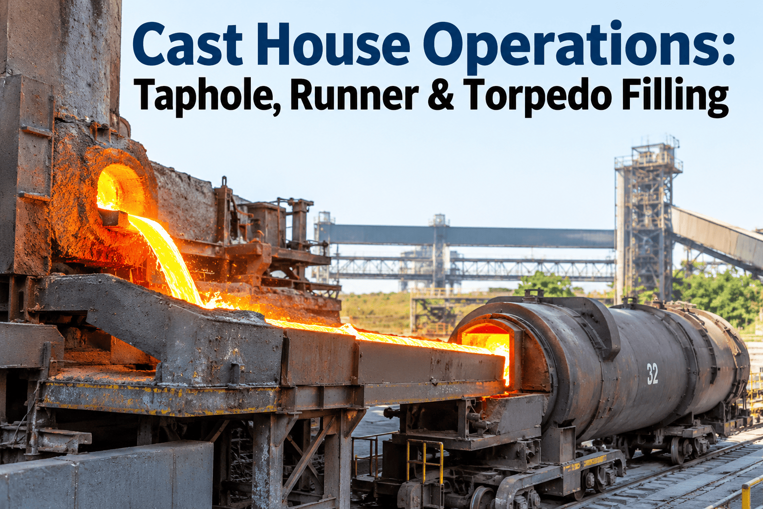
Cast House Operations: Taphole, Runner, and Torpedo Filling Management
Monitor taphole condition, runner and skimmer wear, and torpedo car filling in real time, and turn tap-to-tap consistency from a matter of crew experience into a tracked, repeatable process.
Hot metal path from taphole to torpedo — each stage carries its own wear and monitoring profile
Why Cast House Work Resists Standardization
The Cast House Runs on Judgment Calls That Rarely Get Recorded
Taphole drilling depth, mud gun clay volume, skimmer plate height, and torpedo fill cutoff are all decisions a cast house operator makes by eye and experience, shift after shift, with little of that judgment captured anywhere a reliability team can review it later.
A
Variable Taphole Condition
Clay quality, drilling depth, and taphole angle vary between crews and between taps, and a taphole that drilled clean last shift can behave unpredictably on the next one without any visible warning beforehand.
B
Runner Refractory Wear
Main runner and iron runner castable erodes gradually with every cast, but visual inspection between taps is brief and the true wear depth is often only discovered when a breakout risk is already close.
C
Heat and Visibility
Radiant heat, fume, and glare around an open taphole make continuous close observation physically difficult, so operators rely on brief glances and experience rather than a sustained view of flow behavior.
D
Torpedo Fill Estimation
Fill level in a torpedo car or ladle is commonly judged by tap duration and flow appearance rather than a precise measurement, leaving a persistent risk of overfilling or an inefficient partial load.
Three Zones, Three Failure Modes
Taphole, Runner, and Torpedo Car Wear Differently and Fail Differently
Aspect
Taphole
Runner System
Torpedo Car / Ladle
Primary Function
Controls tap opening, flow rate, and closure timing
Separates iron from slag and directs flow to the car
Receives and transports hot metal to the next process
Key Wear Driver
Clay quality, drilling angle, and repeated thermal cycling
Erosive flow of iron and slag over the castable lining
Thermal cycling and slag/iron buildup on the refractory lining
Typical Failure Mode
Erratic flow, premature closure, or difficult reopening
Localized thinning and breakout risk at erosion points
Refractory spalling and reduced effective payload capacity
Monitoring Difficulty
Direct visual access limited by heat and taphole geometry
Wear depth hidden beneath a hot, moving iron/slag layer
Interior lining condition not visible during normal fill cycles
Operational Focus Areas
What Each Cast House Discipline Actually Controls
Taphole Drilling & Plugging
Drilling depth and angle set relative to furnace hearth profile and prior tap history
Mud gun clay volume and injection pressure calibrated to taphole condition observed on the last close
Tap initiation timing coordinated against hearth level and scheduled cast sequence
Closure quality assessed to judge readiness for the next scheduled tap
Runner & Skimmer Management
Main runner and iron runner castable condition tracked across successive casts
Skimmer plate height adjusted to maintain clean iron/slag separation as flow rate changes
Runner sand and refractory patch maintenance scheduled around wear progression rather than a fixed calendar
Slag runner flow monitored to confirm separation efficiency throughout the tap
Torpedo Car & Ladle Filling
Fill level tracked against car capacity to avoid both overfill risk and inefficient partial loads
Car positioning and switching sequenced against tap flow rate and cast duration
Refractory lining condition logged across fill cycles to plan reline scheduling ahead of failure
Hot metal temperature at fill checked against downstream steelmaking process requirements
From Missed Signal to Cast House Event
How a Small Deviation Becomes a Delay, a Spill, or a Reline
Taphole drilled off the established angle
→
Erratic or premature flow, unplanned tap-to-tap variation
Runner erosion progressing unmonitored
→
Localized thin spot reaches breakout risk without warning
Skimmer height not adjusted for flow change
→
Slag carryover into the iron runner and downstream car
Torpedo fill judged by eye near capacity
→
Overfill spillage risk or an inefficient partial-load run
Mud gun clay volume miscalibrated at close
→
Difficult reopening or premature reopening on the next tap
A Runner That Looks Fine Between Taps Can Still Be Days From a Breakout. The Wear That Matters Is the Wear You Cannot See in a Two-Minute Walk-By.
Continuous cast house monitoring turns a brief visual check into a tracked condition record across every tap.
How iFactory Monitors the Cast House
From Pre-Tap Planning to Post-Tap Condition Review
01
Pre-Tap Planning
Taphole history, hearth level, and cast sequence are reviewed together to set drilling parameters and confirm the runner and torpedo car assignment for the upcoming tap.
02
Drilling & Tap Initiation
Thermal imaging captures taphole opening behavior, comparing flow onset and jet pattern against the profile expected for the drilling parameters used.
03
Flow & Separation Monitoring
Cameras positioned along the runner track iron and slag separation quality continuously through the tap, flagging carryover or flow instability as it happens rather than after the fact.
04
Runner Wear Tracking
Thermal and visual data from each cast is compared against prior casts at the same runner location, building a wear progression trend instead of relying on a single-point inspection.
05
Torpedo Fill Tracking
Fill level is measured directly against car capacity throughout the pour, with an alert issued as the load approaches the safe fill threshold.
06
Post-Tap Condition Review
Taphole closure quality, runner condition, and fill outcome are logged together against the tap, creating a single record the next shift can reference before planning the following tap.
Outcomes Reported by Cast House Teams
What Continuous Monitoring Changes Across a Campaign
Steadier
Tap-to-tap flow consistency across crews and shifts
Earlier
Detection of runner wear approaching breakout risk
Fewer
Slag carryover events reaching the iron runner and car
Reduced
Overfill and spillage incidents at the torpedo car
Planned
Runner and refractory maintenance scheduled ahead of failure
Full Record
Every tap's taphole, runner, and fill condition retained for review
Visual Walk-By vs. Continuous Monitoring
Where the Two Approaches Actually Diverge
Aspect
Manual Walk-By Inspection
iFactory Continuous Monitoring
Observation Window
Brief visual checks between and during taps
Continuous camera and thermal coverage through every tap
Runner Wear Trend
Judged from memory and occasional condition notes
Compared cast over cast at the same runner location automatically
Torpedo Fill Accuracy
Estimated from tap duration and flow appearance
Measured directly against car capacity with a threshold alert
Shift Handover
Verbal notes and memory-based condition summaries
Logged condition record attached to each specific tap
Consistency Across Crews
Varies with individual operator experience and habit
Same monitoring standard applied regardless of which crew is on shift
Maintenance Planning
Reactive, scheduled around visible condition or a fixed calendar
Planned against an actual measured wear progression trend
Field Example
Catching Runner Erosion Two Weeks Before It Would Have Reached Breakout Risk
A cast house team on a large blast furnace had been managing main runner condition through end-of-shift visual checks, with castable repairs scheduled around a rough calendar interval rather than measured wear. Tap-to-tap flow had been consistent, so the runner was not flagged as an immediate concern going into a routine reline planning meeting.
Continuous camera and thermal monitoring across successive taps showed a localized thin spot developing at a known high-erosion point near the skimmer, progressing faster than the surrounding refractory. The wear trend, tracked cast over cast, projected the section would approach a concerning thickness within roughly two weeks if left on the existing repair schedule, well before the next planned reline window.
The cast house team moved a targeted patch repair into the following outage window rather than waiting for the scheduled reline, addressing the thin section directly instead of relining the full runner early. The location is now tracked as a standing high-erosion point in the monitoring system, with wear trend reviewed at every shift handover going forward.
1 spot
High-erosion runner location identified and tracked
~2 weeks
Lead time gained before projected breakout risk
Targeted
Patch repair scheduled instead of an early full reline
Frequently Asked Questions
What Cast House and Ironmaking Teams Ask First
Can cameras and thermal sensors actually survive the heat and dust right next to the taphole and runner?
Cast house monitoring equipment is specified for the radiant heat, dust, and thermal cycling typical of the tap floor, with protective housings and cooling designed for continuous operation rather than occasional exposure. Camera positioning is planned during setup to maintain a clear view of the taphole, runner, and skimmer while staying outside the zone of most direct radiant load and splash risk. Maintenance intervals for lens cleaning and housing inspection are built into the standard operating routine so image quality stays consistent across a full campaign.
Does this replace the cast house operator's judgment, or work alongside it?
It works alongside the operator rather than replacing the tapping decisions they make in real time. The system's role is to make wear progression, flow behavior, and fill level visible as tracked data so operators and shift supervisors have more than a two-minute walk-by to base decisions on. Final tapping, closure, and car-switching decisions remain with the cast house crew, who now have a condition trend and an alert threshold supporting the call rather than memory and a quick visual check alone.
How is runner wear actually measured if the surface is covered by flowing iron during the tap?
Wear tracking relies primarily on the periods between and immediately after taps, when the runner surface is visible, combined with thermal signatures during flow that can indicate thinning at known high-erosion points. Each observation is compared against the same physical location across prior casts rather than judged in isolation, which is what allows a gradual erosion trend to be identified well before the surface shows an obviously critical condition. For runners with a known problem zone, additional imaging angles are configured specifically to keep that location under closer observation.
What does a typical deployment look like for an existing cast house?
Deployment starts with a site walk to identify camera and thermal sensor positions around the taphole, runner, skimmer, and torpedo car loading area that will hold up through a full tap cycle. Initial setup typically takes a few weeks, followed by a calibration period where the system builds a baseline for normal flow, wear, and fill behavior specific to your furnace and cast house layout. To scope equipment placement for your specific cast house geometry,
schedule a walkthrough with the team.
Can torpedo car fill tracking be tied into the broader hot metal logistics schedule?
Yes, fill level and completion timing for each car can be shared with the logistics or dispatch system responsible for coordinating torpedo car movement to the steelmaking shop, so a car's readiness is known as soon as its fill is confirmed rather than after a manual check. This is typically configured during initial setup based on how your plant's existing scheduling system is structured. Details on integrating with an existing logistics workflow are available through
iFactory support.
Stop Managing the Cast House by Memory Between Taps.
Track taphole condition, runner wear, and torpedo fill continuously, and give every shift the same standard to work from.