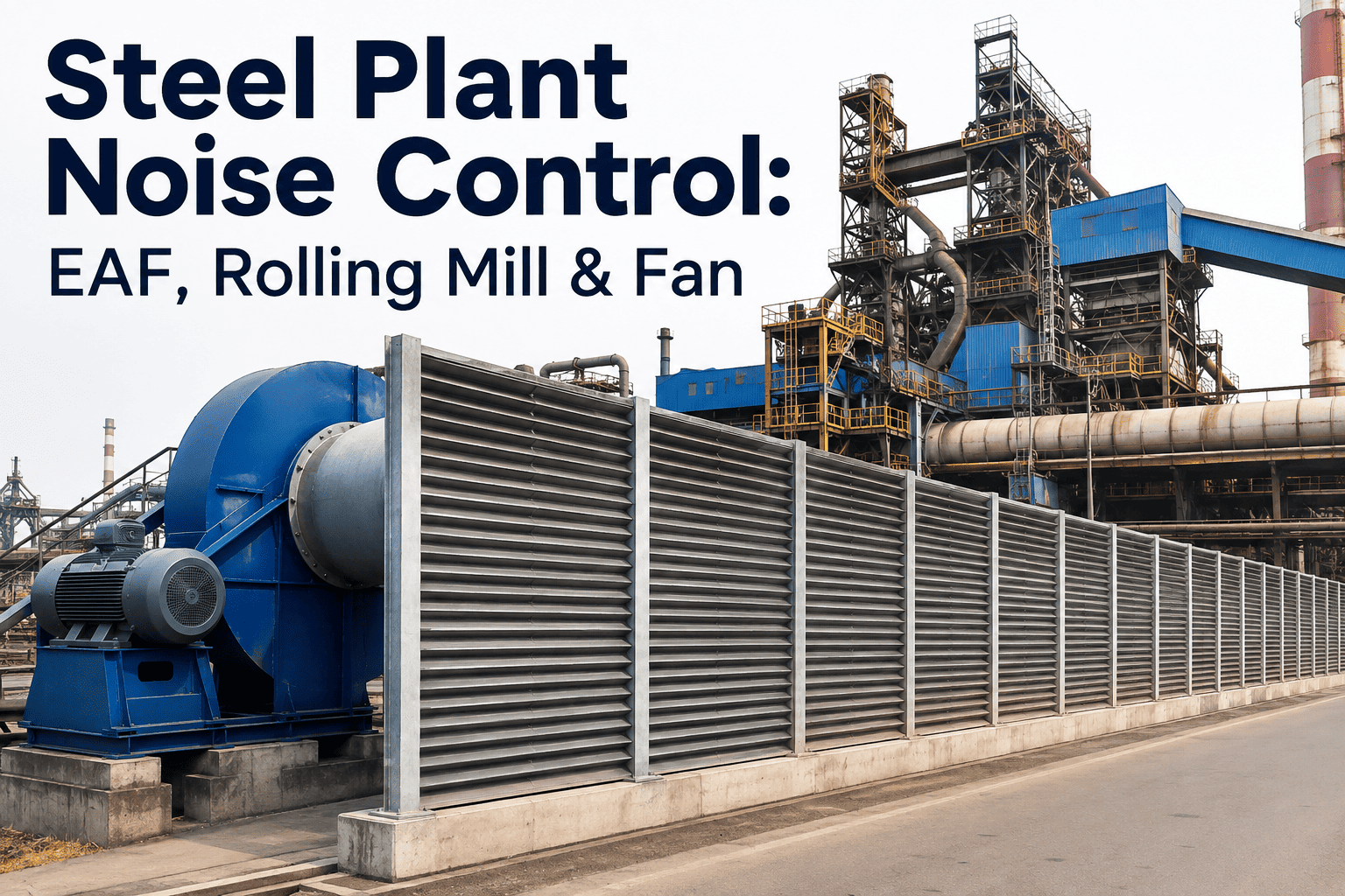
Steel plants generate some of the highest industrial noise levels of any manufacturing environment, with electric arc furnaces producing impulsive sound pressures exceeding 120 decibels during melt-down, rolling mills generating continuous structural and aerodynamic noise above 105 decibels, and high-volume process fans contributing broadband noise that propagates beyond the property boundary. Managing these noise sources requires distinguishing between the physics of sound generation at each piece of equipment, the transmission pathways through structures and air, and the regulatory thresholds that apply differently to worker exposure inside the plant and community impact outside the fence line. Most steel plants treat noise as a compliance checklist item rather than a systematic engineering problem, which leads to expensive retrofits that address symptoms rather than sources. To see how AI-driven noise monitoring transforms this approach, Book a Demo with the iFactory AI environmental team.
Steel Plant Noise Control for EAF, Rolling Mill, and Fan Emissions
iFactory AI delivers continuous noise monitoring and source-specific mitigation analytics for steel plants, mapping EAF arc noise, rolling mill vibration, and fan aerodynamic noise against worker exposure and community compliance limits.
The Source-Path-Receiver Model Applied to Steelmaking Noise
Every noise problem in a steel plant can be decomposed into three components: the source where acoustic energy is generated, the path through which that energy travels to reach a sensitive location, and the receiver who is affected by the noise. Effective noise control requires addressing at least one of these three components, and the most cost-effective solutions typically target the source first, the path second, and the receiver only when source and path treatments are impractical. The framework below maps the major steel plant noise sources to their dominant transmission paths and the receiver categories that experience the impact, providing the structural basis for a systematic mitigation strategy rather than a scattershot approach.
Electric Arc Furnace
Impulsive low-frequency noise generated by the electric arc instability during melt-down, combined with broadband noise from scrap collapse, water cooling hiss, and electrode regulation system movement. The dominant frequency range is 50 to 500 Hertz, with peak sound pressure levels reaching 120 to 135 decibels at one meter from the furnace shell during bore-down.
Airborne Low-Frequency Propagation
Low-frequency sound waves propagate efficiently through air over long distances with minimal attenuation. The EAF building shell provides some high-frequency attenuation but is largely transparent to the dominant low-frequency components. Structural transmission through the furnace foundation and building columns adds a ground-borne vibration component that can be felt in adjacent buildings.
Workers and Community
Operators in the pulpit and on the melt floor experience high impulsive exposure requiring dual hearing protection. Community receivers within 1 to 3 kilometers of the plant experience low-frequency rumble that is particularly noticeable at night when background ambient noise drops. Low-frequency noise is harder to mitigate at the receiver because standard building walls provide minimal attenuation below 200 Hertz.
Rolling Mill
Continuous broadband noise generated by steel-to-roll contact, gear meshing in drive systems, strip vibration and flutter, and cooling water spray impact. Frequency content spans 200 to 4000 Hertz, with overall levels typically 100 to 115 decibels at the operator position. The noise character is steady-state during rolling and drops sharply during gaps and coil changes.
Structural and Airborne Transmission
Rolling mill noise transmits through both airborne paths within the mill building and structural paths through the concrete foundation, isolation pads, and building frame. The structural path is often dominant for low-frequency components below 500 Hertz, while airborne paths dominate above 500 Hertz. Flanking transmission through ventilation openings and roof penetrations allows mid-frequency noise to escape the building envelope.
Operators and Nearby Facilities
Mill operators positioned near the roll bite experience the highest continuous exposure, requiring acoustic enclosures or control rooms. Maintenance personnel working near the mill during shutdowns experience residual structural noise from cooling systems. Nearby administrative buildings and neighboring industrial facilities receive structurally transmitted vibration and low-frequency noise through shared ground or building connections.
Process Fans and Blowers
Aerodynamic noise generated by turbulent airflow at fan blades, vortex shedding at inlet and discharge ducts, and flow-induced vibration of duct walls. Fan noise is predominantly tonal at the blade pass frequency and its harmonics, superimposed on a broadband turbulent noise floor. Large induced draft fans and baghouse exhaust fans typically generate 95 to 110 decibels at the fan housing.
Duct-Borne and Radiated Noise
Fan noise transmits through two distinct paths. Duct-borne noise travels through the ductwork and exits at intake and discharge openings, often with minimal attenuation unless silencers are installed. Radiated noise passes through the fan housing and duct walls directly into the surrounding space. Duct-borne noise is typically the dominant path for community impact because intake and discharge openings often vent directly to atmosphere at elevated positions.
Community Boundaries
Process fans are frequently the dominant source of community noise complaints at steel plant boundaries because their noise exits the plant at elevated stack positions that have clear line-of-sight to distant receivers. The tonal character of fan noise makes it particularly noticeable and annoying to community receivers, even when the overall decibel level is technically below the regulatory limit. Many noise regulations include tonal penalties that add 5 to 10 decibels to the measured level when tonal character is detected.
Steel Plant Noise Levels in Context — Equipment, Limits, and Perception
Understanding the decibel scale in the context of steel plant equipment is essential for prioritizing mitigation efforts. The scale below maps the noise output of major steelmaking equipment against regulatory exposure limits and common perception thresholds. Note that the decibel scale is logarithmic, meaning a 10 decibel increase represents a tenfold increase in acoustic energy and is perceived by humans as approximately a doubling of loudness. This logarithmic relationship means that reducing a 120 decibel EAF to 110 decibels eliminates 90 percent of the acoustic energy, even though the numerical reduction appears modest.
The gap between equipment noise levels and community limits is enormous, typically 50 to 70 decibels, which explains why steel plant noise control is technically challenging and expensive. No single mitigation measure can bridge this gap. It requires sequential attenuation across the source, path, and receiver, with each element contributing 10 to 20 decibels of reduction. The logarithmic math means that three 10-decibel reductions applied in sequence achieve a 30-decibel total reduction, which eliminates 99.9 percent of the original acoustic energy.
Electric Arc Furnace Noise — Characteristics and Treatment Strategies
EAF noise is the most challenging source in a steel plant because it combines impulsive high-amplitude low-frequency sound with structural vibration transmission. The impulsive character means that standard time-averaged decibel measurements underestimate the subjective impact, because the ear is more sensitive to sudden sounds than to steady sounds at the same average level. The treatment strategies below address the EAF noise problem at the source and path levels, ranked by typical cost-effectiveness for both worker exposure and community impact reduction.
Furnace Building Acoustic Enclosure
The EAF building shell acts as the primary barrier between the furnace and both workers and the community. Upgrading the building from a standard industrial enclosure to a designed acoustic enclosure involves adding mass to the walls and roof, sealing all penetrations, and treating ventilation openings with acoustic louvers or silencers. Typical upgrades include adding a minimum 25 millimeter density board to interior walls, installing double-glazed acoustic observation windows, and sealing door perimeters with compression gaskets. This treatment typically achieves 15 to 25 decibels of reduction at mid to high frequencies but only 5 to 10 decibels at the dominant low frequencies below 200 Hertz where the EAF produces most of its acoustic energy.
Reduction: 15–25 dB (mid-high freq), 5–10 dB (low freq)Furnace Shell Damping Treatment
The EAF shell radiates sound like a loudspeaker cone when excited by the internal arc pressure fluctuations. Applying constrained layer damping to the furnace shell converts vibrational energy into heat through shear deformation in the damping material, reducing the sound radiated by the shell itself. This is a source treatment that reduces the noise before it enters the building space. Constrained layer damping is most effective at the shell resonant frequencies, which typically fall in the 80 to 300 Hertz range where the building enclosure is least effective. The challenge is that damping treatments must withstand the extreme thermal cycling and mechanical abuse of the furnace shell environment.
Reduction: 5–10 dB at shell resonant frequenciesDedicated Operator Control Rooms
For worker exposure reduction, the most reliable approach is to remove the operator from the high-noise environment entirely. Modern EAF control rooms are designed to achieve NC-35 to NC-40 noise criteria inside the room while the furnace operates at full power outside. This requires isolated slab-on-grade foundations, floating floor systems, double-wall construction with an air gap, acoustic doors, and silenced ventilation systems. The control room approach does not reduce community noise but eliminates the worker exposure problem with near-certainty, reducing exposure from 120-plus decibels to below 45 decibels inside the room. For monitoring integration with control room systems, Book a Demo with iFactory AI.
Reduction: 70+ dB for worker exposure inside the roomRolling Mill Noise — Structural Vibration and Enclosure Design Principles
Rolling mill noise differs from EAF noise in that it is predominantly continuous rather than impulsive, and it spans a wider frequency range from 200 to 4000 Hertz. The continuous nature means that standard time-averaged measurements accurately represent the exposure, but the wider frequency range means that effective mitigation requires treatments that perform across multiple octaves rather than targeting a specific low-frequency band. The structural transmission path is particularly important for rolling mills because the massive concrete foundations that support the mill stands efficiently conduct low-frequency vibration into the ground and adjacent building structures.
| Noise Component | Generation Mechanism | Dominant Frequency | Primary Path | Most Effective Treatment |
|---|---|---|---|---|
| Roll Bite Noise | Steel-to-roll contact, friction, and plastic deformation | 500–2000 Hz | Airborne from roll gap | Partial enclosure around roll bite with acoustic absorption interior |
| Gear Mesh Noise | Tooth contact in drive reducers and pinion stands | 200–1000 Hz | Structural through gearbox housing and airborne | Enclosure of gearbox with vibration isolation mounts |
| Strip Flutter | Vibration of the steel strip between stands | 100–500 Hz | Airborne radiation from vibrating strip surface | Tension control optimization and strip damping devices |
| Cooling Water Spray | High-pressure water impact on hot steel | 1000–4000 Hz | Airborne from spray nozzles | Nozzle shrouds and spray chamber enclosure |
| Motor and Drive Noise | Electromagnetic hum, bearing noise, cooling fans | 100–2000 Hz | Airborne and structural through motor foundation | Acoustic enclosure for motor, vibration isolation pads |
The most effective rolling mill noise mitigation strategy is a partial acoustic enclosure that covers the roll bite area while allowing visual access for operators and material flow. These enclosures are constructed with heavy-gauge outer panels for sound transmission loss, acoustic absorption material on the interior to reduce reverberant buildup, and transparent viewing panels made of laminated glass for operator visibility. A well-designed partial enclosure around the roll bite typically achieves 15 to 20 decibels of insertion loss, reducing operator position noise from 110 decibels to approximately 90 to 95 decibels, which may still require hearing protection but reduces the exposure dose dramatically.
Industrial Fan Noise — Aerodynamic Control and Silencer Selection
Process fans and blowers in steel plants present a noise control challenge that is fundamentally different from EAF or rolling mill noise. Fan noise is dominated by tonal components at the blade pass frequency, which makes it more noticeable and more heavily penalized by noise regulations that include tonal adjustments. The aerodynamic nature of the source means that the most effective treatments target the airflow path itself, using silencers and duct modifications to attenuate noise before it exits to the atmosphere or enters occupied spaces.
Inlet Silencers
Inlet silencers are installed on the fan suction side and are typically the highest-priority treatment for community noise because the inlet opening often draws air from outside the building and radiates noise directly to the surrounding area. The silencer consists of a rectangular or circular housing containing parallel acoustic baffles lined with sound-absorbing material. The length and density of the baffles determine the attenuation performance, with typical industrial fan inlet silencers providing 20 to 35 decibels of insertion loss across the 250 to 2000 Hertz range. For EAF off-gas fans, inlet silencers must also account for particulate loading and potential condensation, requiring washable or replaceable liner materials.
Typical Attenuation: 20–35 dBDischarge Silencers
Discharge silencers serve the same function on the fan outlet side and are critical when the discharge duct vents directly to atmosphere through a stack. Discharge silencers must be designed for the higher air temperatures and pressures present on the discharge side, which affects baffle structural requirements and liner material selection. In applications where the discharge connects to a long duct run before exiting the building, the duct itself provides some natural attenuation, and the discharge silencer may be sized smaller than the inlet silencer. However, if the discharge exits through a short stack or roof penetration, a full-size discharge silencer is essential to prevent the stack from becoming the dominant community noise source.
Typical Attenuation: 20–30 dBAerodynamic Source Modifications
Before investing in silencers, it is worth evaluating whether the fan itself can be modified to reduce noise generation at the source. Increasing the clearance between blade tips and the fan housing reduces tip clearance noise, which is often a dominant component. Installing inlet guide vanes or changing the blade count can shift the blade pass frequency away from structural resonances that amplify specific tones. Replacing an inefficient fan with a properly sized unit operating closer to its best efficiency point reduces turbulence and associated broadband noise. These source modifications typically cost less than silencers and provide 3 to 8 decibels of reduction, which may not be sufficient alone but reduces the silencer size requirement and total system cost. For fan noise assessment support, contact iFactory Support.
Typical Reduction: 3–8 dB at sourceWorker Exposure vs Community Impact — Two Different Regulatory Worlds
Steel plant noise management must satisfy two fundamentally different regulatory frameworks simultaneously. Worker exposure is governed by occupational health regulations that set maximum permissible exposure limits based on duration, while community impact is governed by environmental regulations that set absolute limits at property boundaries regardless of the source. These two frameworks use different measurement metrics, different time averaging periods, and different penalty structures, which means a plant can be fully compliant for worker exposure while simultaneously violating community noise limits, or vice versa. The comparison below clarifies the key differences that drive separate but parallel noise management programs for the two receiver categories.
Occupational Health Framework
Environmental Regulatory Framework
Continuous Noise Monitoring for Compliance and Operational Insight
Periodic noise surveys, typically conducted annually for compliance purposes, provide snapshot measurements that may or may not represent the true worst-case noise conditions at a steel plant. EAF noise varies dramatically depending on the scrap mix, with heavy melt producing different noise characteristics than light shred. Rolling mill noise varies with product mix and rolling speed. Fan noise varies with process demand and ambient temperature. Continuous noise monitoring systems address this variability by measuring noise levels at critical locations around the clock, capturing peak events that periodic surveys would miss and providing the data needed to correlate noise levels with specific operating conditions.
Community Noise Compliance Verification
Permanent noise monitoring stations installed at the plant property boundary measure Leq, L10, L90, and Lmax continuously, with 15-minute or 1-hour averaging intervals aligned with regulatory requirements. Weather stations co-located with noise monitors record wind speed, wind direction, temperature, and humidity because these atmospheric conditions significantly affect sound propagation and must be documented to validate compliance measurements. When noise levels approach or exceed limits, the system correlates the exceedance with plant operating data to identify which equipment or process was responsible, enabling targeted operational adjustments rather than blanket production curtailment.
Worker Exposure and Source Characterization
Fixed noise monitors installed at critical worker locations such as EAF pulpit, rolling mill operator platform, and fan deck areas provide continuous exposure data that supplements or replaces personal dosimetry for area-based assessments. More importantly, in-plant monitoring provides the time-synchronized data needed to characterize the noise signature of each equipment source under different operating conditions. By correlating noise time histories with process data, engineers can identify which operating parameters have the greatest influence on noise output and target optimization efforts accordingly. This correlation capability is what transforms noise monitoring from a compliance reporting tool into an operational improvement tool.
Steel Plant Noise Control — FAQs for Environmental and Reliability Engineers
Why is EAF noise so difficult to control compared to other steel plant equipment?
EAF noise is difficult to control because it is dominated by low-frequency impulsive sound energy below 200 Hertz. Low-frequency sound waves have long wavelengths that pass through standard building walls and acoustic enclosures with minimal attenuation. A typical industrial building wall that provides 30 decibels of attenuation at 1000 Hertz may provide only 5 to 10 decibels of attenuation at 100 Hertz. Additionally, the impulsive character of EAF noise means that time-averaged measurements underestimate the subjective impact, and the structural vibration component transmits through the foundation and building columns, bypassing airborne barriers entirely. Effective EAF noise control requires addressing the source through shell damping, the structure through vibration isolation, and the airborne path through massive enclosure walls, making it significantly more complex and expensive than controlling broadband mid-frequency noise from fans or rolling mills. For a site-specific assessment, Book a Demo with our environmental engineering team.
Can we rely on hearing protection alone to meet worker noise compliance requirements?
Hearing protection is a valid component of a hearing conservation program under OSHA regulations, but it cannot be the sole method of noise control for several reasons. First, OSHA requires that hearing protection be used only when engineering and administrative controls are not feasible, meaning that feasible engineering controls must be implemented first. Second, the real-world effectiveness of hearing protection is typically 50 to 70 percent of the labeled Noise Reduction Rating due to improper fit, inconsistent wear, and communication requirements that cause workers to remove protection temporarily. Third, hearing protection does nothing for non-auditory effects of noise exposure, including stress responses, cardiovascular effects, and communication interference that reduces situational awareness and safety. Engineering controls like enclosures, silencers, and damping treatments provide reliable, consistent reduction that does not depend on worker behavior. For hearing conservation program support, reach out through iFactory Support.
What is a tonal penalty and how does it affect our community noise compliance?
A tonal penalty is an adjustment added to the measured noise level when the noise contains a prominent tonal component that makes it more annoying than a broadband noise at the same level. Many community noise regulations, including most local ordinances and some state-level rules, require that when a tone is detected in the noise spectrum, typically defined as a narrow-band level that exceeds the adjacent broadband level by 5 or more decibels, a penalty of 5 to 10 decibels is added to the measured level for compliance evaluation. Steel plant fan noise is particularly susceptible to tonal penalties because the blade pass frequency and its harmonics create clear tonal components in the spectrum. A plant measuring 64 dBA at the boundary might be assessed at 69 to 74 dBA after tonal penalty, pushing it over a 65 dBA limit even though the raw measurement appeared compliant. Eliminating the tone through silencer design or aerodynamic modifications is often more cost-effective than trying to reduce the overall level by the penalty amount.
How does weather affect community noise measurements at the plant boundary?
Weather significantly affects sound propagation from steel plants to community boundaries through three primary mechanisms. Wind gradient effects cause sound waves to bend downward when wind blows from the plant toward the community, increasing received levels by 5 to 15 decibels compared to calm conditions. Temperature inversion layers, common during clear nights, trap sound near the ground and prevent normal upward dispersion, causing similar increases in received levels. Atmospheric absorption reduces high-frequency sound more than low-frequency sound, meaning EAF low-frequency noise propagates further in humid conditions while fan mid-frequency noise is attenuated more. Because of these weather effects, compliance measurements must be conducted under defined meteorological conditions, and continuous monitoring systems must co-record weather data to interpret noise readings correctly. A noise exceedance during downwind conditions may not represent a violation if the measurement protocol requires upwind or calm-wind measurement conditions.
What is the typical return on investment for steel plant noise mitigation projects?
ROI for noise mitigation is difficult to express in traditional financial terms because the primary benefits are risk avoidance rather than revenue generation. However, the cost categories that contribute to ROI include avoided regulatory fines, which can range from tens of thousands to hundreds of thousands of dollars per violation depending on the jurisdiction; avoided legal costs from community noise lawsuits, which can exceed a million dollars in extended proceedings; reduced worker compensation claims for noise-induced hearing loss, which average approximately twenty thousand dollars per claim; and avoided production restrictions that regulators may impose on plants that cannot demonstrate compliance. For plants facing active community complaints or regulatory enforcement actions, the ROI of noise mitigation is typically positive within 12 to 24 months when these avoided costs are quantified. For plants without active pressure, the ROI calculation is more qualitative but reflects growing regulatory enforcement trends and increasing community tolerance expectations. To build a business case for noise monitoring, Book a Demo with iFactory AI.
Turn Noise Compliance from a Periodic Report into Continuous Assurance
Connect with iFactory AI to deploy continuous noise monitoring at your plant boundary and critical worker locations, with automated source correlation that identifies exactly which equipment is driving your noise exposure and community impact levels.