Every ring frame spindle carries a rotating mass at speeds between 15,000 and 25,000 RPM. When that mass is not centred on the rotation axis, the spindle generates a radial force that repeats once every revolution, and at 20,000 RPM that means more than 330 force cycles per second. The force is small at first, but it grows with speed squared, so doubling the speed quadruples the load on the bearing, the bolster and the blade. Detecting imbalance early is the fastest way to protect bearing life, reduce end breaks and keep yarn quality consistent across every position on the frame. Mills building a spindle-level monitoring program can book a walkthrough with iFactory AI to see imbalance data mapped per position.
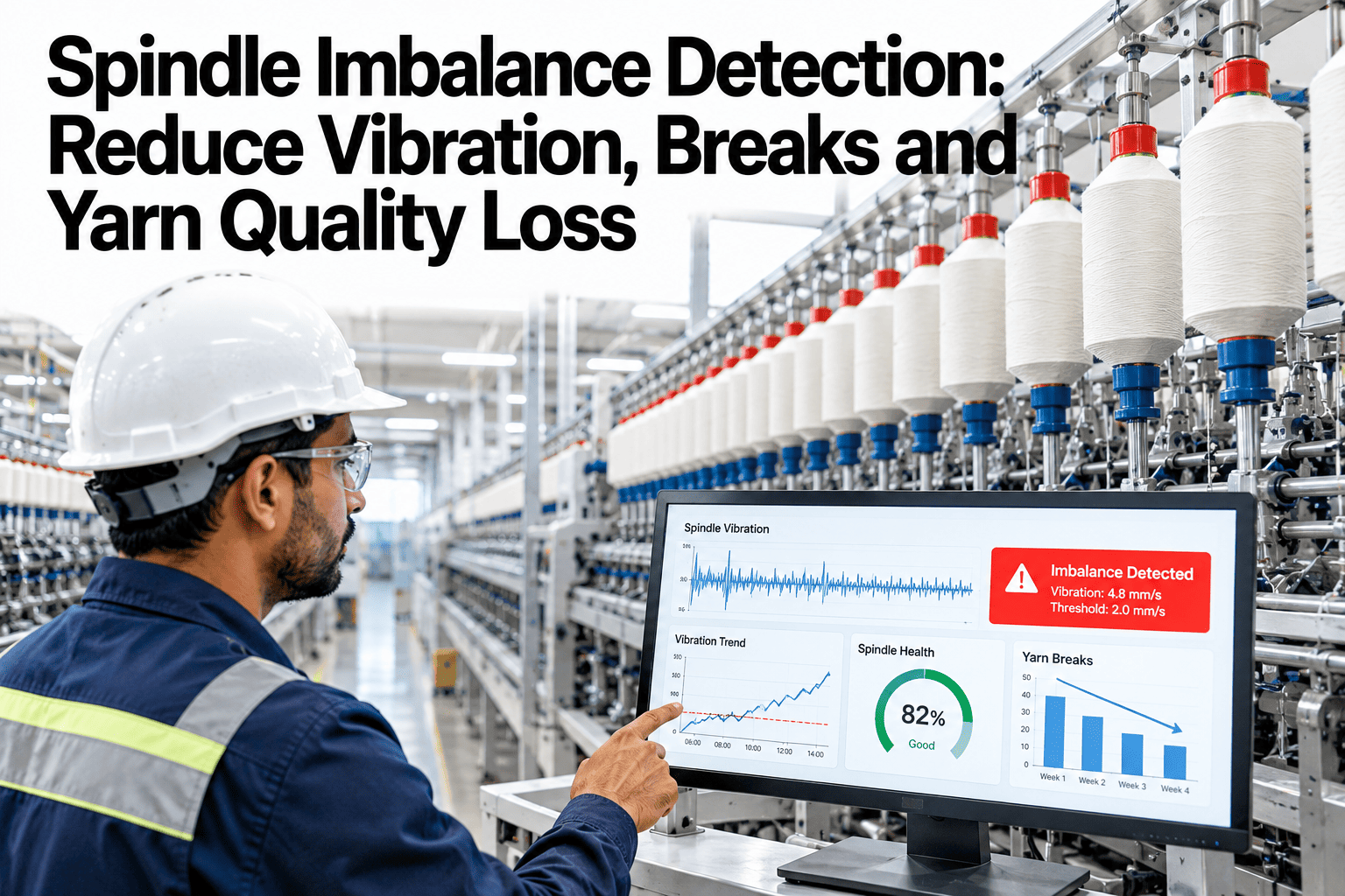
Spindle Imbalance Detection: Reduce Vibration, Breaks and Yarn Quality Loss
Connect vibration patterns to individual spindle positions, identify mass imbalance before it damages bearings, and trace yarn defects back to the spindle that caused them. iFactory AI makes the data visible.
What Spindle Imbalance Actually Does
Imbalance means the centre of mass of the rotating assembly does not sit on the geometric axis of rotation. The offset may come from a bent blade, uneven residual yarn on the wharve, a replacement component machined slightly off-centre, or a bearing pack that was not seated squarely during installation.
The result is a centrifugal force directed outward from the heavy side. That force rotates with the spindle and pushes the blade sideways once per revolution. At operating speed the force is continuous and periodic, and it does three things at the same time.
Loads the bearing unevenly
The radial force pushes the blade against one side of the bolster bore on every revolution. The oil film on that side thins, metal-to-metal contact starts earlier, and bearing wear accelerates. A spindle running with moderate imbalance can lose half its bearing life compared to a balanced spindle at the same speed.
Disturbs cop formation
The wobble transfers to the cop. Yarn layers wind unevenly, the cop surface becomes irregular, and unwinding tension at the next process stage varies from layer to layer. The downstream machine sees more breaks and more off-standard packages.
Changes balloon geometry
A wobbling spindle shifts the balloon anchor point once per revolution. The balloon shape oscillates, traveller speed varies, and yarn tension fluctuates. The tension variation shows up as a periodic thick-thin fault in the yarn and as a rise in Uster CV percentage.
All three effects happen simultaneously, and they reinforce each other. A spindle with imbalance does not just wear out faster. It produces worse yarn while it wears out, and the quality problem is often invisible until the downstream process complains. Teams that want to see how imbalance data connects to their yarn quality records can schedule a data walkthrough with iFactory AI.
Where Imbalance Comes From
Not every imbalance is a manufacturing defect. Many of the most common causes are introduced during normal maintenance, operation or material handling.
Bent blade
A blade that takes a slight bend during handling, doffing or transport shifts the mass distribution permanently. Even a deflection too small to see with the naked eye produces a measurable 1x vibration at operating speed.
Off-centre bearing pack
A bearing pack pressed into the bolster at a slight angle changes the effective rotation axis. The blade then orbits around a point that is not its geometric centre, creating a dynamic imbalance that worsens with speed.
Residual yarn on wharve
Yarn that wraps around the wharve during a break and is not fully cleared adds mass on one side of the spindle. The additional mass is small, but at 20,000 RPM the resulting force is significant enough to drive a measurable vibration increase.
Machining tolerance drift
Replacement blades or wharves machined at the edge of specification may pass a static inspection but produce dynamic imbalance at full speed. Batch-level quality checks on incoming components prevent this source.
Bolster bore wear
After many bearing pack changes the bolster bore elongates or loses concentricity. The blade no longer rotates in the designed centre line, and the resulting eccentricity behaves like a permanent imbalance that persists through pack renewals.
Cop buildup asymmetry
A traverse mechanism that has drifted from calibration builds yarn on one side of the cop heavier than the other. The cop itself becomes the unbalanced mass, and the imbalance grows as the cop builds through the doff cycle.
Reading the 1x Vibration Signature
Imbalance has a distinctive vibration fingerprint. It shows up as a strong peak at the 1x frequency, which is the running speed of the spindle. At 18,000 RPM the 1x frequency is 300 Hz. At 22,000 RPM it is approximately 367 Hz. The peak appears in the radial direction because the centrifugal force acts outward from the rotation axis.
1x radial amplitude
The amplitude of the 1x peak rises with the square of speed. If a spindle shows a moderate 1x peak at 15,000 RPM, the same imbalance produces roughly double the peak height at 21,000 RPM. This speed-squared relationship is the single most reliable marker of mass imbalance.
Phase angle stability
A true imbalance produces a stable phase angle at the 1x frequency. If the heavy spot is at the 90-degree position, the phase reading stays near 90 degrees across measurements. A drifting phase suggests a loose component rather than a fixed imbalance, and the corrective action is different.
Absence of bearing frequencies
Pure imbalance does not produce peaks at the ball pass frequency outer race (BPFO) or inner race (BPFI). If those peaks are also present, the spindle has both an imbalance and a bearing defect, and the maintenance plan needs to address both.
RMS velocity over time
Plotting the overall RMS vibration velocity per spindle over weeks reveals whether an imbalance is static, where the level stays constant, or progressive, where the level climbs as the imbalance damages the bearing and the bearing damage adds its own vibration component on top.
Understanding these markers lets the maintenance team separate imbalance from bearing damage, eccentricity and external sources like drive belt faults. That separation determines whether the right action is a blade swap, a balance correction, a pack change or a structural check. Teams building vibration analysis capability can reach iFactory support for guidance on configuring frequency-band alerts.
Imbalance, Yarn Quality and the Data That Connects Them
The strongest case for detecting imbalance early is not the bearing cost alone. It is the yarn quality loss that accumulates silently while the imbalance runs unchecked.
When the analysis platform links vibration data to quality data at the spindle level, each quality excursion carries a mechanical explanation. The quality team stops chasing count or draft settings and the maintenance team stops treating vibration as a standalone metric. Both teams work from one data set. Mills that want to build this link on their own production data can book a correlation session with iFactory AI.
Map Imbalance Across Every Position
Book a 30-minute session and see how iFactory AI plots vibration amplitude, 1x frequency and quality deviations against individual spindle positions on your ring frames.
Corrective Actions by Imbalance Source
Knowing that a spindle is imbalanced is not enough. The correction depends on why it is imbalanced. Applying the wrong fix wastes a good component or leaves the root cause in place.
A blade with a permanent bend cannot be straightened reliably at production speed. Replace it with a new or reconditioned blade that passes a runout check. Record the replacement in the spindle history so the vibration trend resets cleanly.
Stop the spindle, remove the cop, and clear all residual yarn from the wharve and blade base. This is the simplest and cheapest correction. If the vibration returns after cleaning, the cause is elsewhere.
Remove the bearing pack and inspect the seating surface. If the bolster bore is clean and round, press a new pack using the correct insertion tool and verify alignment. If the bore is worn, the bolster itself needs attention.
A bolster with a worn bore needs re-boring or replacement. Continuing to press packs into a worn bore wastes packs and creates a recurring imbalance that the vibration data will flag again within weeks of each change.
Introduce a runout and weight check for incoming blades and wharves. Reject components outside the tolerance band before they reach the frame. Prevention at goods receipt is cheaper than correction at the spindle.
A vibration monitoring system that tracks the 1x amplitude before and after each corrective action proves whether the fix worked. If the amplitude drops to baseline, the root cause was correctly identified. If it stays elevated, there is a second source. This feedback loop makes the maintenance team progressively better at diagnosing imbalance, and mills wanting to set up that loop can request a workflow session from iFactory AI.
Building a Per-Spindle Imbalance Baseline
A single vibration reading tells you the state right now. A baseline built from two to four weeks of data tells you what normal looks like for each individual spindle, and that baseline is what makes detection work.
Collect raw data
Sensors record vibration amplitude, 1x peak height and overall RMS at each spindle position. No thresholds are set yet. The goal is to capture the natural variation across positions, shifts and count changes.
Identify position variation
Some positions consistently read higher than others due to structural resonance, proximity to the drive end or floor conditions. These positional differences are normal and must be captured in the baseline rather than treated as faults.
Set per-spindle bands
Calculate the mean and standard deviation for each spindle position. Set the watch threshold at two standard deviations above the mean and the alert threshold at three. These thresholds respect the individual character of each position.
Validate against known events
Compare alerts to maintenance records. Every spindle that triggered an alert and was later found to have a real imbalance confirms the threshold. Every false alarm refines it. After one cycle of validation the system is tuned to your frames.
Per-spindle baselines eliminate the false alarms that come from applying one threshold to every position on a frame. When operators trust the alerts, they act on them. When alerts are noisy, they ignore them. The baseline is what earns that trust, and iFactory AI builds it automatically from the data it collects. Mills ready to start a baseline period can book a scoping session to define the pilot frames.
What iFactory AI Brings to Spindle Monitoring
iFactory AI is smart manufacturing and industrial software delivered as a pre-configured NVIDIA AI server. It racks into your plant network, connects to sensors and existing systems, and goes live without a long integration project.
Per-position tracking
Every spindle carries its own vibration profile, baseline and alert history. The dashboard shows the entire frame as a position map, colour-coded by severity, so the maintenance team can see at a glance which spindles need attention and which are running clean.
Quality correlation
Vibration data links to yarn quality records at the spindle level. When a CV increase appears on a specific bobbin, the platform checks whether the corresponding spindle has a rising vibration trend. The match gives the maintenance team a quality-backed reason to act.
Maintenance integration
Alerts flow into the mill's existing CMMS or ERP as work orders with the spindle position, fault type and recommended action pre-filled. The maintenance planner does not need to interpret raw vibration data to schedule the right repair at the right time.
Deployment timeline
A working pilot on four to eight frames typically reaches production monitoring within six to twelve weeks. The turnkey server model means no custom software development, no cloud dependency and no long commissioning cycle. Rack, plug, connect sensors, go live.
Mills that want to understand the deployment path for their specific frame layout and sensor infrastructure can arrange a scoping call with the iFactory team.
Frequently Asked Questions
How is imbalance different from bearing damage in the vibration data?
Imbalance shows as a dominant peak at the 1x running speed frequency with a stable phase angle. Bearing damage produces peaks at the ball pass frequencies, which are much higher than 1x and often modulated by sidebands. The two patterns are spectrally distinct and the iFactory AI platform classifies them automatically. Book a demo to see fault classification on live spindle data.
Can imbalance be corrected without removing the spindle from the frame?
It depends on the cause. Residual yarn on the wharve can be cleaned in place. A bent blade requires removal and replacement. An off-centre bearing pack requires dismounting and reseating. The vibration data tells the maintenance team which correction to apply before they start, saving time and avoiding trial-and-error swaps. Book a walkthrough to see corrective workflows mapped to vibration patterns.
Does monitoring slow down the frame or affect production?
No. Sensors collect data while the frame runs at full production speed. There is no interruption to the spinning cycle, no speed reduction and no added load on the drive system. Sensor installation takes place during a planned maintenance window and once installed the monitoring is continuous and passive. Book a session to discuss sensor placement for your frame model.
How quickly can the system detect a new imbalance after it develops?
A sudden imbalance event, such as yarn wrapping the wharve, shows up in the next measurement cycle. A gradual imbalance, such as a slowly bending blade, is detected through trend analysis over days to weeks. The per-spindle baseline means even a small change stands out against that spindle's history. Ask iFactory support about detection timing for your specific monitoring interval.
Does iFactory AI work with all ring frame manufacturers?
The platform is manufacturer-agnostic. It connects to sensors mounted on the frame structure, not to the frame's own control system. Whether the mill runs frames from Rieter, Saurer, Toyota or Lakshmi, the vibration data follows the same physics and the same analysis applies. Book a compatibility check for your installed frame base.
Detect Imbalance Before It Costs You Yarn
iFactory AI maps vibration, quality and maintenance data to every spindle position on your ring frames. Book a session scoped to your frame layout and see the data working.