The continuous caster is the single point in steelmaking where every downstream product inherits its surface quality DNA. A transverse crack on a slab face that goes undetected at the caster exit becomes a lamination in the hot-rolled coil, a surface break in the cold-rolled strip, and ultimately a customer rejection at the automotive stamping press — three to four process stages and weeks of production time after the defect originated. A longitudinal corner crack on a billet that escapes the casting bay becomes a seam in the wire rod, a fatigue initiation point in the drawn wire, and eventually a field failure in the spring or fastener it was used to manufacture. Catching caster-origin defects at the source is not simply a quality improvement initiative — it is the only strategy that prevents a single solidification event from generating cascading costs across the entire downstream value chain. iFactory's AI vision camera platform deploys at continuous caster exits to inspect every slab and billet surface at production speed, detecting transverse cracks, longitudinal cracks, oscillation marks, corner cracks, inclusions, and scale pits with over 95 percent accuracy at temperatures exceeding 800°C — replacing the 5 to 15 percent visual sampling coverage that scarfing bay operators can realistically provide under production pressure with 100 percent automated surface coverage on every cast product leaving the caster.
See How iFactory's AI Vision Platform Catches Caster-Origin Defects Before Downstream Processing
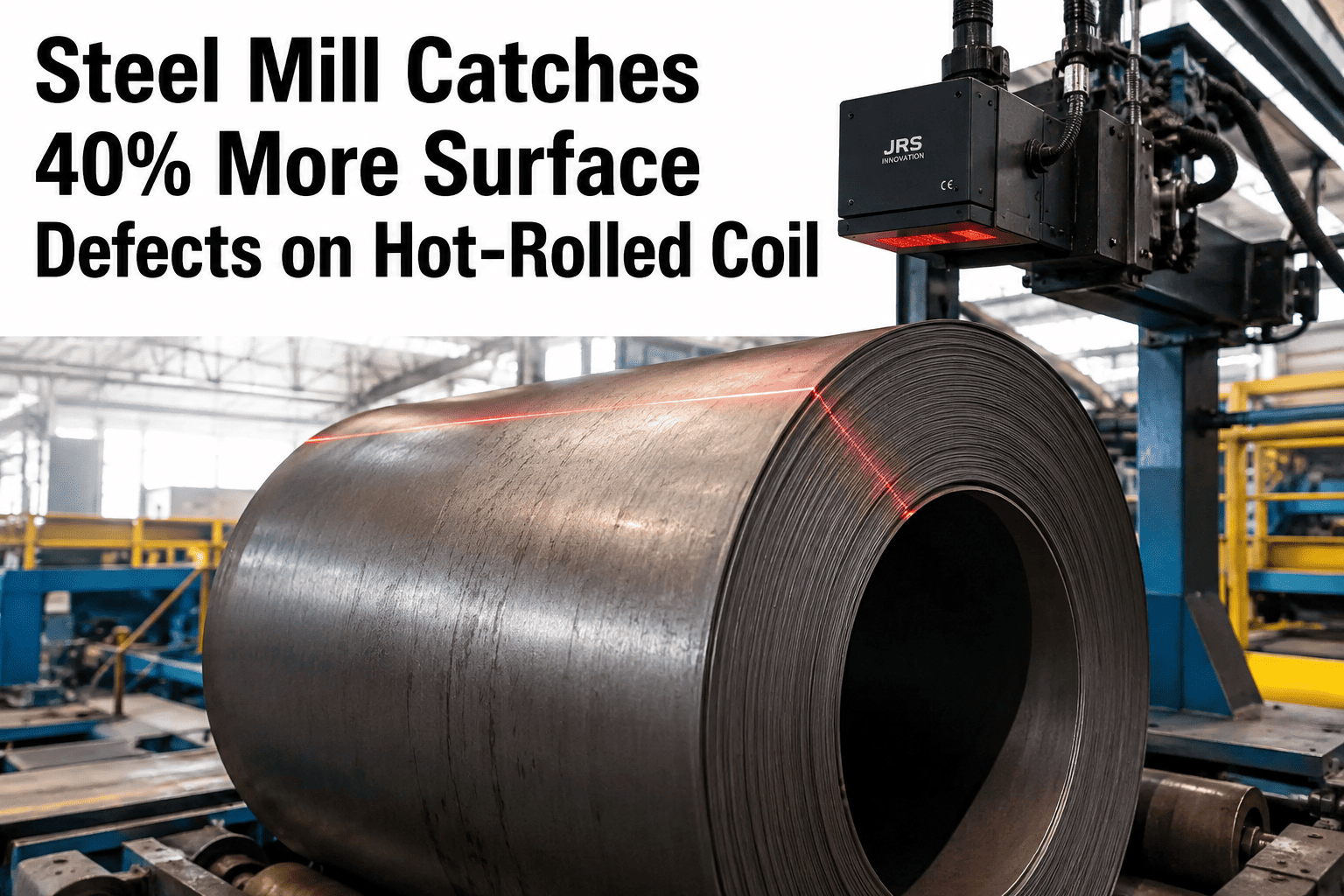
iFactory's edge-deployed AI vision cameras inspect slab and billet surfaces at caster exit temperatures — detecting transverse cracks, longitudinal cracks, oscillation marks, corner defects, and inclusions in real time, before defective material enters the reheat furnace, rolling mill, or wire rod block.
Why Slab and Billet Inspection at the Caster Exit Changes the Economics of Steel Quality
Scarfing bay operators inspect a fraction of slab surfaces under time pressure, using visual judgment in environments with residual heat radiation, steam, and scale dust. Defects on unseen faces, internal areas, or below human contrast detection thresholds pass directly into the downstream process without any quality record.
iFactory's multi-camera deployment at caster exit inspects all six slab faces and all four billet surfaces in a single pass at production speed. Every square centimeter of every product is imaged, classified, and recorded — with no dependency on operator attention, shift fatigue, or lighting conditions in the caster environment.
Visual inspections generate paper notes or verbal handoffs that do not link defect observations to specific slab positions, caster strand identifiers, heat sequence numbers, or upstream casting parameters. When downstream rejects occur, tracing the defect back to its casting origin requires forensic investigation that rarely reaches a definitive root cause.
Every defect detection event is recorded with slab ID, strand number, heat sequence, caster position, defect type, severity score, and timestamp — creating an unbroken traceability chain from casting event to downstream processing decision. When downstream rejects occur, the root cause investigation retrieves the complete inspection record in minutes, not days.
Scarfing and conditioning decisions — whether to scarf, how deeply, or whether to reject a slab — are made by operators under production schedule pressure with incomplete surface information. The result is systematic over-scarfing on product that does not need conditioning and under-scarfing on product that does, generating both yield loss and downstream rejection costs simultaneously.
iFactory's AI vision system generates a precise defect map for every slab and billet, specifying defect type, location, and depth estimate — enabling conditioning recommendations that are scarf-only-where-needed rather than blanket treatment. Automated conditioning decisions reduce scarfing yield loss while ensuring every defect requiring treatment is addressed before the product enters the rolling process.
Ready to close the detection gap at your continuous caster exit? Book a Demo to see how iFactory's AI vision platform delivers 100% slab and billet surface coverage in your specific caster environment, with defect traceability that connects every surface event to its casting parameter origin.
6 Critical Caster-Origin Defect Types iFactory AI Vision Detects on Slabs and Billets
Transverse Surface Cracks
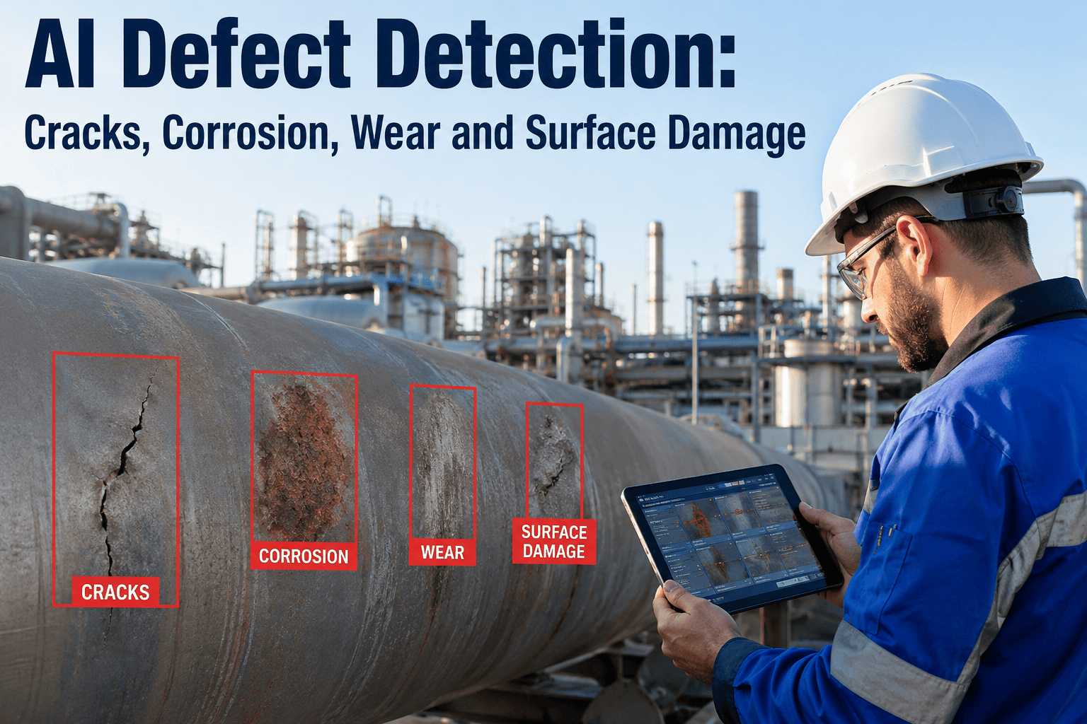
Highest Consequence DefectTransverse cracks form perpendicular to the casting direction from thermal shock, mold level instability, or excessive casting speed during solidification. They are the most destructive caster-origin defect because they propagate through every downstream rolling pass — becoming laminations in flat product, seams in long product, and catastrophic failure initiation points in structural applications. iFactory's AI vision cameras detect transverse cracks at widths as narrow as 0.1mm on slab and billet surfaces at temperatures exceeding 800°C, classifying each crack by length, width, and estimated depth to enable appropriate conditioning decisions before the product enters the reheat furnace.
Longitudinal Surface and Corner Cracks
Wire Rod and Structural Grade RiskLongitudinal cracks run parallel to the casting direction and form along slab faces or billet corners from uneven cooling, mold taper mismatch, or guide roll misalignment. Corner cracks on billets are particularly problematic in wire rod production because the rolling process does not remove or blend corner defects — they become seams that run the full length of the wire and represent fatigue failure risks in high-stress applications including springs, fasteners, and structural wire. iFactory's camera deployment covers all four billet corners and slab edges with dedicated imaging angles that optimise contrast for longitudinal crack detection.
Oscillation Mark Irregularities
Process Parameter IndicatorOscillation marks are regular transverse depressions formed by mold oscillation during solidification — a normal casting feature when uniform, but a defect indicator when irregular in depth, spacing, or shape. Deep or irregular oscillation marks trap flux and create preferential sites for transverse crack initiation, particularly at the meniscus. iFactory's AI vision system characterises oscillation mark depth and regularity as a continuous process monitoring metric, flagging abnormal oscillation mark patterns that indicate mold flux performance issues, mold taper wear, or oscillation parameter drift before they generate visible crack defects on the slab surface.
Non-Metallic Inclusions and Surface Slivers
Automotive Grade Rejection CauseAlumina, silica, and slag inclusions entrapped in the steel matrix during casting present as surface slivers, stringer defects, or subsurface features that break through to the surface during rolling. In automotive-grade flat product, inclusions cause paint adhesion failures and stamping press cracking that trigger the most expensive customer quality claims in steel production. iFactory's AI vision cameras detect inclusion surface manifestations on slab faces at caster exit, correlating inclusion cluster patterns with specific caster sequences, tundish positions, and heat numbers — providing the traceability data needed to identify tundish nozzle erosion, slag carry-over events, and ladle refractory wear as the upstream sources driving inclusion defect frequency.
Scale Pits and Rolled-In Scale
Surface Finish and Coating Defect SourceScale formation on slab and billet surfaces during solidification and cooling creates pits and scale adherence patterns that, when rolled into the steel during hot processing, produce the surface pitting and rolled-in scale defects that drive cosmetic rejection in coated product applications. Detecting scale pit distribution and density at caster exit enables descaling parameter optimisation before rolling — reducing the proportion of surface area requiring remediation and preventing scale-induced surface defects from appearing on the finished strip or section. iFactory's AI vision classifies scale pit severity across the full slab face, generating per-product conditioning recommendations that specify descaling intensity by surface zone rather than applying blanket treatment.
Pinhole Porosity and Subsurface Features
Pressure Vessel and API Grade RiskPinhole porosity — small gas voids trapped near the slab surface during solidification — presents as a cluster of fine pits on the slab face that indicate hydrogen pickup, argon injection irregularities, or steel cleanliness problems originating in the melt shop. In pressure vessel, pipe, and API-grade steel applications, subsurface porosity is a critical quality rejection criterion that becomes detectable at the surface only after the outer solidified shell is removed by scarfing or light rolling. iFactory's AI vision system detects surface pinhole patterns and classifies their distribution relative to established acceptance thresholds for each product grade — triggering conditional inspection hold decisions for grades where subsurface porosity criteria apply.
Want to see iFactory's defect classification accuracy on your specific slab or billet grade and defect portfolio? Book a Demo to see live detection on actual continuous casting footage matched to your operating temperature range and casting speed.
Measured Quality and Cost Impact: What AI Slab and Billet Inspection Delivers
Deploy 100% Slab and Billet Surface Coverage at Your Continuous Caster Exit
iFactory's AI vision camera platform inspects every slab and billet surface at production speed, generates per-product defect maps with heat sequence traceability, and delivers automated conditioning recommendations — giving your casting operation the quality control infrastructure that prevents caster-origin defects from reaching your downstream processes and your customers.
What Metallurgical Experts Say About AI-Driven Caster Surface Inspection
"The quality economics of continuous casting are fundamentally asymmetric — defects cost exponentially more to address downstream than they do at the source. A transverse crack on a slab that costs $200 in scarfing material and 10 minutes of conditioning time at the caster exit costs $15,000 to $40,000 in hot mill reject, reheating energy, and customer claim cost if it reaches the customer as finished product. The challenge has always been detection at source — because 800°C slab surfaces in a caster bay environment defeat human inspection in ways that no training programme can overcome. AI vision systems that operate at production temperature and speed, maintain sub-0.2mm detection sensitivity across the full slab face, and connect every detected event to upstream casting parameters represent the first genuinely adequate solution to this problem that the industry has produced. The facilities that deploy this technology at the caster rather than waiting until the hot mill exit are preventing defects from accumulating processing cost rather than discovering them after that cost has already been spent."
5 Steps to Deploying AI Vision Inspection at Your Continuous Caster Exit
Caster Environment Assessment and Camera Position Design
Continuous caster environments present the most challenging imaging conditions in steelmaking — 800°C to 950°C slab surface temperatures producing near-infrared thermal radiation, steam from secondary cooling water, scale dust, and significant vibration from casting equipment and torch cutting. The first deployment step is a physical assessment of the caster layout to determine camera housing placement, illumination strategy, thermal protection requirements, and the slab transport speed profile that determines required camera frame rate. iFactory's engineering team conducts this assessment on-site, producing a camera positioning design and housing specification that addresses all environmental challenges before hardware procurement begins.
Defect Library Development and AI Model Training
iFactory's AI defect classification models are pre-trained on steel-specific defect image libraries covering the standard casting defect categories — transverse cracks, longitudinal cracks, oscillation marks, inclusions, scale pits, and corner defects. After hardware installation, the models are fine-tuned on defect samples from your specific caster, steel grades, and operating conditions to achieve the classification accuracy required for your quality acceptance standards. This fine-tuning phase typically requires 200 to 400 labelled defect images per critical defect class and is completed within three to four weeks of system commissioning, after which detection accuracy is validated against your existing quality records before live operation begins.
Shadow Mode Validation Against Existing Quality Records
Before any automated quality hold decision authority is activated, iFactory operates the AI inspection system in shadow mode — running live inspection and logging all detection events without triggering conditioning or hold flags. Shadow mode outputs are compared against existing scarfing records, downstream reject data, and customer claim history to validate that the AI system is detecting the defect events that matter and classifying them consistently with your quality standards. This parallel validation period, typically four to six weeks, builds production team confidence in the system's judgment and establishes the detection sensitivity and false positive rate baselines that govern live operation parameters.
Live Inspection Activation with Conditioning Recommendation Integration
Following shadow mode validation, iFactory activates live inspection with quality hold and conditioning recommendation authority. The system generates per-slab defect maps that specify defect type, location coordinates, and estimated severity for every product leaving the caster — feeding conditioning recommendations to the scarfing bay in real time. Simultaneously, the inspection data flows into the plant's Level 2 quality tracking system via API, linking each defect event to the slab ID, strand number, heat sequence, and casting parameters active at the time of detection. The first four weeks of live operation are monitored closely for false positive rates, conditioning decision accuracy, and downstream quality improvement indicators.
Defect Trend Analysis and Casting Process Improvement Integration
The full value of AI slab and billet inspection emerges after the first three to six months of accumulated inspection data when defect pattern analysis connects surface quality events to specific casting parameters, equipment conditions, and operational variables. iFactory's inspection database enables metallurgical analysis that identifies which casting speeds, mold flux types, cooling profiles, or tundish conditions correlate with elevated transverse crack rates, inclusion cluster events, or oscillation mark irregularities — providing the engineering data needed to address root causes in the casting process rather than simply detecting and conditioning the symptoms. This continuous improvement loop transforms the inspection system from a detection tool into a process optimisation platform that reduces defect frequency at source over time.
Frequently Asked Questions
Stop Paying Downstream Processing Costs on Defective Slabs and Billets — Catch Them at the Caster
iFactory's AI vision camera platform provides 100% slab and billet surface coverage at continuous caster exit temperatures, generating per-product defect maps with heat sequence traceability and automated conditioning recommendations — preventing caster-origin defects from entering your downstream process and reaching your customers.