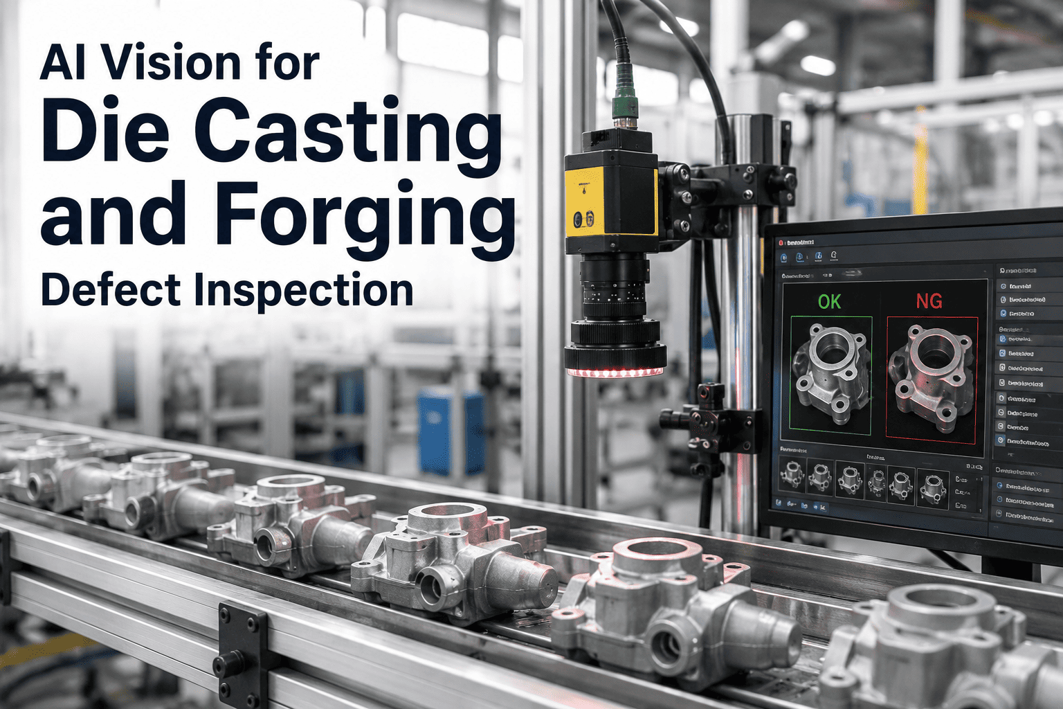
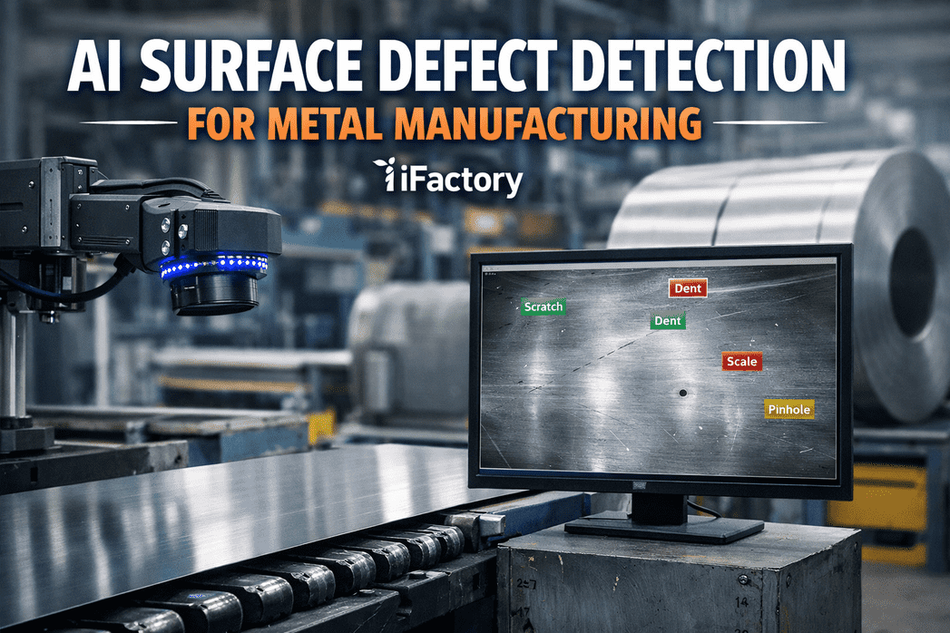
A small aluminum die casting can cycle off the machine every 15 to 90 seconds depending on part size, and cooling time, not injection speed, dominates that cycle. That pace is exactly what makes visual inspection so hard to hold consistently — a human inspector working a die casting cell for a full shift is being asked to catch cold shuts, laps, porosity, flash, and surface inclusions on complex, often reflective geometry, at a rate no person can sustain without fatigue eroding the catch rate by the end of the shift. Scrap rates in controlled die casting environments run 2 to 5 percent even under good process control, and a defect caught after secondary machining costs far more than the same defect caught at the press. AI vision is now being placed directly at die casting and forging cells to inspect every part at cycle speed. To see how this fits your production line, book a demo.
PROCESS-SPECIFIC · DIE CASTING & FORGING · CYCLE-SPEED INSPECTION
Every Part, Every Cycle, at the Speed Your Press Already Runs
Cold shuts, laps, porosity, flash, and surface inclusions form in seconds during casting and forging, and they need to be caught at that same pace. AI vision inspects complex, reflective geometry at full cycle speed without the fatigue curve a human inspector can't avoid.
15–90 sec
Typical die casting shot cycle time, meaning every inspection decision has to happen at that same pace
2–5%
Typical scrap rate in controlled die casting production, even under good process discipline
1.2%
Maximum porosity by volume many automotive OEMs allow on critical structural die cast components
91–96%
Typical detection accuracy range for AI vision systems trained on casting and forging defect classes
THE DEFECT MAP EVERY INSPECTOR IS WORKING FROM
What Actually Goes Wrong on the Cast or Forged Surface
Casting and forging fail in specific, well-understood ways, and each defect class has a different root cause upstream in the process. A vision system trained on these categories is checking for the actual failure modes your process produces, not a generic surface-anomaly score.
Cold Shuts and Misruns
Two metal fronts meet but fail to fuse, usually from low pouring temperature or poor gating design, leaving a visible seam that represents a structural weak point under load.
Laps and Folds
Metal folds back on itself during forging rather than flowing fully into the die, most common in complex geometries with multiple flow paths or where metal velocity drops off.
Porosity and Gas Holes
Trapped gas or shrinkage during solidification leaves internal or surface-breaking voids, the single most common die casting defect and a direct driver of leak-test and structural failures.
Flash and Parting Line Defects
Excess metal escapes at the parting line or die seam under injection pressure, a dimensional and finishing problem that also signals die wear or clamping force drift worth flagging upstream.
Surface Inclusions
Slag, dross, or oxide contamination becomes trapped in the surface during pour or forge, appearing as discoloration or embedded particles that compromise finish and, in some cases, structural integrity.
Cracks and Hot Tears
Restricted shrinkage or uneven cooling opens a crack at the casting's weakest structural point, often at a fillet radius or wall thickness transition, and is among the highest-consequence defects to miss.
See these defect classes detected on your own parts
iFactory configures die casting and forging inspection around your specific alloy, part geometry, and defect history — not a generic surface-anomaly model.
WHY THIS INSPECTION PROBLEM IS HARDER THAN IT LOOKS
Complex Geometry, Reflective Surfaces, and No Time to Look Twice
Casting and forging inspection combines three challenges that make manual visual inspection especially hard to sustain, and that make a generic vision system a poor fit without process-specific tuning.
01
Cycle Speed Leaves No Room for a Second Look
With shot cycles as short as 15 seconds, an inspector has only the time between parts to evaluate a full surface, and that window shrinks further on high-cavitation dies producing multiple parts per shot.
02
Complex Geometry Hides Defects in Plain Sight
Ribs, bosses, undercuts, and draft angles create shadowed and angled surfaces where a cold shut or lap can sit just out of a fixed viewing angle, the exact geometry die casting is chosen for in the first place.
03
Reflective and As-Cast Surfaces Confuse Fixed Lighting
Bright aluminum and zinc surfaces scatter light unpredictably, and a lighting setup tuned for one alloy or finish frequently misses defects or throws false positives on another.
MANUAL INSPECTION VS. AI VISION AT CYCLE SPEED
What Changes When Every Part Gets the Same Look
The defect standard does not change — cold shuts, laps, porosity, and flash still need to be caught against the same acceptance criteria. What changes is whether that standard holds on part one thousand the same way it held on part one.
| Inspection Factor |
Manual Visual Inspection |
AI Vision at Cycle Speed |
| Parts inspected per shift |
Sampled, or full coverage with fatigue-driven drop-off |
100% of parts, same standard part one and part ten thousand |
| Complex geometry coverage |
Limited to visible angles under fixed shop lighting |
Multi-angle imaging tuned to ribs, bosses, and undercuts |
| Defect-to-process linkage |
Defect logged, root cause investigated separately |
Defect type and location linked toward likely process cause |
| Consistency across shifts |
Varies by inspector experience and time of day |
Same detection standard applied on every shift |
| Response to a defect spike |
Often identified only after downstream failure or claim |
Real-time alert when defect rate on a cavity or die trends up |
HOW A PART GETS INSPECTED WITHOUT SLOWING THE PRESS
From Ejection to Pass/Fail Decision, Inside the Cycle
Inspection is positioned in the part-handling sequence that already exists, at ejection or immediately after trim, so the vision system adds a decision point rather than a new station that slows the line.
1
Part Presented at Ejection or Trim
Cameras are positioned where the part is already handled by the robot or conveyor, capturing the surface as it exits the die or forging press without adding a separate inspection stop.
2
Multi-Angle Imaging Captures the Full Geometry
Multiple camera angles and calibrated lighting cover ribs, bosses, undercuts, and the parting line, addressing the shadowed-surface problem that limits a fixed single-angle view.
3
Defect Classification Against the Part's Known Defect Library
The model classifies any detected anomaly against the alloy- and part-specific defect categories it was trained on, distinguishing a true cold shut or lap from harmless as-cast surface texture.
4
Pass, Reject, or Rework Decision Within the Cycle
The system returns a decision fast enough to route the part before the next shot completes, keeping the inspection step inside the existing cycle time rather than adding to it.
5
Defect Trends Mapped Back to Cavity and Shot Parameters
Defects are logged by cavity, die, and shift, surfacing patterns like a single cavity trending toward porosity, which points maintenance and process engineering toward the root cause instead of just the symptom.
WHY UNSUPERVISED DETECTION MATTERS FOR THIS PROCESS
You Don't Need a Library of Labeled Defects to Get Started
Most foundries and forge shops don't have a large, labeled archive of defective parts sitting around, because defective parts are the exception, not the rule, and nobody has historically been photographing and cataloging scrap for machine learning purposes. That has traditionally been the blocker for deploying vision-based inspection: the model needs examples of what bad looks like, and bad parts are rare by design in a well-run process.
The practical answer is an approach that learns what a good part looks like from production parts you're already making, rather than requiring a defect-labeled dataset before deployment. A small set of known defect examples still helps calibrate severity thresholds, but it is not a precondition for going live. This matters specifically for die casting and forging operations, where defect rates in the low single digits mean waiting to accumulate a meaningful labeled defect set could take months of production the line doesn't have time to spare.
BEFORE YOU START
What Quality and Process Engineering Should Have Ready
Facilities that move fastest from evaluation to a working pilot generally arrive with a clear picture of their current defect mix and part portfolio, rather than starting the conversation from scratch.
1
Current Defect and Scrap Data
Existing scrap rate by defect type and by cavity or die, which becomes the baseline a pilot is measured against.
2
Part Portfolio and Alloy Mix
Which parts, alloys, and finishes run through the cell in highest volume, since geometry and reflectance both shape camera and lighting configuration.
3
Ejection and Trim Station Layout
Where parts are currently handled after the shot, since inspection is positioned inside that existing handling sequence rather than as a new stop.
4
Known Defect Examples, If Available
Any existing photos or physical samples of past defects, which speed up severity calibration even though they are not required to start.
Scope a pilot around your part portfolio
A short working session maps your current defect mix, part geometry, and cell layout against what a pilot deployment would look like for your facility.
FREQUENTLY ASKED QUESTIONS
What Foundries and Forge Shops Ask Before Adopting AI Vision
Can this actually keep up with a 15-second shot cycle without slowing the line down?
Yes — the inspection decision is designed to complete inside the existing cycle time rather than adding a new station, which is why cameras are positioned at the point where the part handling robot or conveyor already presents the part after ejection or trim. Detection latency is scoped during pilot setup against your specific cycle time and cavity count, since a high-cavitation die producing multiple parts per shot has a tighter window than a single-cavity setup. The goal is inspection that fits inside the cycle your press already runs, not a new bottleneck.
Contact our support team to review cycle-time compatibility for your specific press and part mix.
We don't have a large library of defective part images — can we still deploy this?
Yes, this is one of the more common starting points for foundries and forge shops, since defective parts are the exception in a well-controlled process and most facilities have never systematically photographed scrap. Detection is built around learning what a good part looks like from your normal production output, rather than requiring a large labeled defect dataset before going live. A handful of known defect examples, if you have them, helps calibrate severity thresholds faster, but they are not a precondition for starting a pilot.
Book a demo to see how detection is calibrated without a pre-existing defect library.
How does the system handle complex geometry with ribs, bosses, and undercuts that hide defects at certain angles?
Multi-angle camera configuration and calibrated lighting are set up specifically for the part geometry in question, covering the shadowed and angled surfaces that a single fixed camera or standard shop lighting would miss. This is configured during pilot setup against your actual part CAD or physical samples, rather than assuming a generic camera arrangement will cover every feature. Parts with particularly aggressive undercuts or deep pockets may need additional camera angles or a secondary inspection pass, which is scoped as part of the initial configuration.
Contact our support team to review camera coverage for your specific part geometry.
Can the system tell the difference between a real defect and normal as-cast surface texture?
Distinguishing a genuine cold shut, lap, or inclusion from harmless as-cast texture, parting line witness marks, or minor cosmetic variation is one of the core calibration steps during pilot deployment, since a system that flags too aggressively creates as much disruption as one that misses real defects. Detection is tuned against your specific alloy, surface finish, and acceptance criteria rather than a one-size-fits-all sensitivity threshold, and false-positive rates are actively reviewed and adjusted during the pilot period before the system is trusted for autonomous pass/reject decisions.
Book a demo to see false-positive calibration on sample parts from your process.
How long does it take to get a pilot running on our die casting or forging cell?
Timelines depend on part complexity, cavity count, and how much historical defect data is available, but a scoped pilot on a single cell or press is generally the fastest way to validate detection accuracy against your own scrap and defect baseline before wider rollout is considered. Because the system integrates with the part handling already in place at ejection or trim, most of the pilot timeline goes toward camera and lighting calibration for your specific parts rather than new conveyor or robotics work.
Contact our support team to scope a pilot timeline for your cell.
EVERY PART, THE SAME STANDARD, AT PRESS SPEED
Bring 100% Inspection to Your Die Casting or Forging Cell
Cold shuts, laps, porosity, flash, and inclusions form fast and hide in complex geometry. iFactory configures AI vision around your alloy, your parts, and your press's actual cycle time.