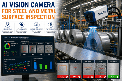
Surface finish is the quality characteristic that ends customer relationships fastest — a scratch on a polished metal trim piece, a dig mark on an automotive windscreen, a sink depression on a consumer electronics housing. These defects share one trait that makes them uniquely difficult to inspect: they are invisible under the wrong lighting. A scratch on polished stainless steel disappears completely under diffuse illumination and becomes clearly visible under darkfield grazing light. A sink mark on a glossy plastic panel cannot be seen head-on but reveals itself as a shadow under angled structured light. Photometric stereo, the technique of capturing the same surface under sequential directional illumination and computing surface normals from the reflected intensity differences, is the optical method that consistently makes these defects visible regardless of material. iFactory combines photometric stereo lighting with deep learning inspection models trained specifically for metal, glass, and plastic surface characteristics — with deployment specifications at iFactory support.
Surface Finish AI Inspection · Metal · Glass · Plastic
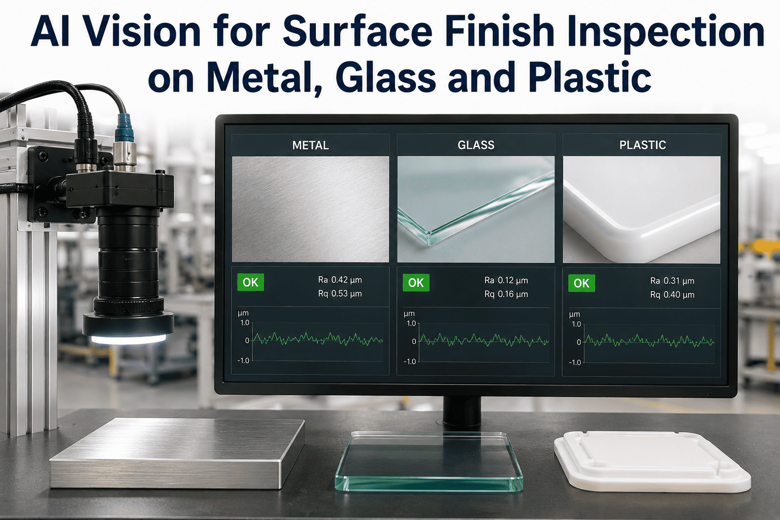
AI Vision for Surface Finish Inspection on Metal, Glass and Plastic
Photometric stereo lighting sequences reveal scratches, dents, orange peel, and texture variations that flat illumination hides completely. Deep learning models classify surface finish defects at line speed — on reflective metal, transparent glass, and glossy plastic — with detection sensitivity down to 50 microns.
Glass
Transparency creates reflection and transmission noise
Scratches · Chips · Inclusions · Optical distortion · Dig marks
Transmitted + Polarized + Darkfield
Plastic
Gloss and texture variation creates false signals
Sink marks · Orange peel · Flow lines · Flash · Contamination
Dome + Structured Light + Grazing Angle
Why Standard Vision Fails
The Lighting Problem That Makes Surface Defects Invisible to Flat Illumination
The failure mode of conventional machine vision on surface finish inspection is not a software problem — it is a physics problem. Surface defects on reflective, transparent, and glossy materials interact with light in ways that flat illumination cannot resolve. Understanding the optical mechanisms explains why photometric stereo is not a premium option for these materials; it is an engineering requirement.
The Specular Reflection Problem
When a flat light source illuminates a polished metal surface, specular reflection — the mirror-like bounce of light off a smooth surface — produces a bright hotspot directly in the camera's view. The hotspot saturates the image sensor in that zone, making the pixel values uniform maximum white. A scratch in the hotspot area is genuinely invisible because the scratch and the surrounding surface both appear as maximum white. Darkfield illumination, which angles the light source at 5 to 15 degrees from horizontal, means the smooth surface reflects the light away from the camera — the surface appears dark. The scratch edge scatters light back toward the camera and appears bright against the dark background. The contrast reversal makes the scratch visible at sensitivities down to 0.05mm width.
The Transparency Problem
Glass Surface
Flat reflected light: surface + substrate combined
Transmitted light: internal defects visible
Glass presents two simultaneous inspection challenges: the surface can be scratched or chipped, and the material can contain internal inclusions, bubbles, or optical distortions. Reflected light inspection captures surface defects but creates noise from internal reflections. Transmitted light inspection (backlit through the glass) reveals internal defects but washes out surface condition. Polarized illumination filters specular reflections from the front surface, allowing the camera to see through to subsurface features. A complete glass inspection station sequences through reflected darkfield, transmitted backlight, and cross-polarized illumination to cover all three defect categories without a false positive from optical interference between imaging modes.
The Gloss Variation Problem
Glossy Plastic Surface
Flat light: gloss variation mimics defect
Structured light: height deviation detected
Glossy plastic surfaces have inherent gloss variation from mold release agents, resin lot differences, and cooling rate variation across a single shot. Under flat illumination, these natural gloss variations produce intensity differences that look identical to a scratch or surface stain — producing high false positive rates that make the inspection results unreliable. Structured light projection — fringe patterns projected onto the surface and decoded into a height map — is immune to gloss variation because it measures surface topography rather than reflected intensity. A sink mark is a genuine height deviation and appears in the structured light data. A gloss variation has no height component and does not appear. This is why sink mark detection on plastic requires structured light or photometric stereo, not intensity-based imaging.
Photometric Stereo Explained
How Photometric Stereo Reveals What Single-Angle Lighting Hides
Photometric stereo is the technique of illuminating the same surface from four or more directional angles in rapid sequence and using the reflected intensity differences between images to compute the surface normal at every pixel. The normal map encodes surface orientation — not just brightness — which is why photometric stereo detects surface relief that intensity imaging misses entirely.
01
Sequential Directional Illumination
Four LED arrays — North, South, East, West relative to the part — fire in microsecond sequence while a high-speed camera captures one image per illumination direction. Total acquisition time for all four images is typically 8 to 40 milliseconds, within a single production cycle stop.
02
Surface Normal Computation
Each pixel across the four images has a different intensity depending on the direction of the light source relative to the local surface orientation. The mathematical relationship between the four intensity values uniquely determines the surface normal vector at that pixel — the precise direction the surface faces at that point.
03
Surface Normal Map Generation
The per-pixel normal vectors are rendered as a normal map — an image where color encodes surface orientation rather than brightness. A scratch on a polished surface is an abrupt change in surface orientation that appears as a high-contrast edge in the normal map regardless of whether it was visible in the intensity image under any single lighting angle.
04
AI Model Defect Classification
The normal map, combined with the intensity images from each illumination direction, is fed to a deep learning model trained on defect images captured under the same photometric stereo configuration. The model classifies defect type, scores severity, marks defect location on the part, and issues pass/fail in under 50ms from acquisition complete.
50 microns
Minimum scratch width detectable on polished metal
8–40ms
Total photometric stereo acquisition time per part
4–8
Illumination directions for full surface normal coverage
99.7%
Classification accuracy on trained surface defect classes
Material-Specific Inspection
How the AI Inspection Stack Differs Across Metal, Glass, and Plastic
The optical physics of each material class requires a different inspection architecture. The AI model, the camera specification, and the lighting configuration all change based on material. A system configured for polished stainless steel will produce unreliable results on automotive glass without reconfiguration — and reliable results with the right one.
Defect Catalog
Scratch
From 10–20 microns
Cross-polarized darkfield
Chip / Edge damage
From 20 microns length
Backlight + darkfield
Inclusion / Bubble
From 0.1mm diameter
Transmitted backlight
Optical distortion
Wavefront deviation
Schlieren / grid target
Dig mark
From 0.05mm area
Darkfield oblique
Coating defect
Coverage gap, pin hole
UV fluorescence
Camera Configuration
Resolution12–65MP area scan with HDR; 2k–8k line scan for large panels
LensHigh-NA macro for micro-scratch; telecentric for edge measurement
Primary lightingTransmitted LED backlight (internal defects) + reflected darkfield (surface)
SecondaryCross-polarization to eliminate specular reflection from front surface
Special challengeHeater lines in automotive glazing must be trained as non-defect patterns
Defect Catalog
Sink mark
From 0.1mm depth
Dome + structured light
Orange peel
Texture deviation
Photometric stereo
Flow / weld line
From 0.2mm length
Grazing angle
Flash
From 0.1mm thickness
Backlight silhouette
Contamination
Color + spectral
Multi-spectral RGB
Gloss deviation
Measured vs baseline
Photometric stereo
Camera Configuration
Resolution8–29MP area scan; line scan for large panels with continuous motion
LensStandard or telecentric depending on dimensional requirements
Primary lightingDome for gloss suppression + grazing structured light for topography
SecondaryMulti-spectral for color contamination invisible in standard RGB
Special challengeBlack and dark-colored parts require UV or near-IR imaging for scratch contrast
That scratch your customer returned last month was there when it left your line. It was invisible under your current lighting. Let us show you what photometric stereo would have caught.
iFactory designs surface finish inspection systems specific to your material, defect types, and line speed — and has it running on your parts within six weeks.
Detection Sensitivity Reference
What Surface Finish AI Vision Actually Detects: Minimum Defect Sizes by Material and Lighting Mode
Detection sensitivity is a function of three variables: the optical resolution of the imaging system, the contrast enhancement provided by the lighting configuration, and the training quality of the AI model. The values below represent production-validated performance on iFactory deployments — not laboratory conditions.
Defect Type
Material
Lighting Mode
Min. Detection Size
False Positive Risk
Surface scratch
Polished metal
Darkfield
0.05mm width
Low
Surface scratch
Automotive glass
Cross-polarized darkfield
10–20 microns
Medium
Dent / Depression
Sheet metal
Photometric stereo
0.1mm depth
Low
Sink mark
Glossy plastic
Structured light
0.1mm depth
Low
Internal inclusion
Glass / transparent
Transmitted backlight
0.1mm diameter
Low
Orange peel
Painted / plastic
Photometric stereo
Texture deviation vs baseline
Low
Chip / Edge break
Glass
Darkfield + backlight
20 microns length
Medium
Flash (parting line)
Injection plastic
Backlight silhouette
0.1mm thickness
Low
False positive risk rating based on material surface variation. Medium indicates operator review recommended for detections near the minimum size threshold. Production deployments typically operate at thresholds 2x the minimum to sustain false positive rates below 0.5%.
Field Example
Consumer Electronics Manufacturer: Surface Scratch Customer Returns Eliminated After Photometric Stereo Deployment
A contract manufacturer producing aluminum housing panels for a premium consumer electronics OEM was running a bright-field overhead camera system for surface finish inspection. The system was reliable for detecting contamination and large visible scratches but was consistently missing fine scratches in the range of 0.05 to 0.2mm width on the anodized aluminum finish — the exact defect class that the OEM's customers were returning units for. Customer return rate for cosmetic surface finish was 1.4%, representing 2,800 units returned per quarter and $210,000 in reverse logistics, reprocessing, and replacement costs. The defects were confirmed as present at the time of shipment when returned units were examined under the correct darkfield lighting in the quality lab — lighting the production inspection station simply did not use.
iFactory replaced the overhead brightfield camera with a photometric stereo station using an 8-direction LED ring at 8 degrees from horizontal, a 20MP global shutter camera, and a deep learning model trained on 1,200 labeled scratch images across five severity grades. The model was configured to automatically reject Grades 3 to 5 and route Grades 1 to 2 to operator review on a display showing the normal map with the defect highlighted. In the first full quarter of production under the new system, zero surface scratch customer returns were recorded. The line's cosmetic rejection rate at final inspection increased from 0.3% (the previous inspection system's catch rate) to 2.1% — which represented the actual defect rate the line had been producing all along but shipping through without detection.
1.4% to 0%
Customer return rate for surface scratch, one quarter
$210K
Annual logistics and replacement cost eliminated
0.05mm
Minimum scratch width detected under darkfield photometric stereo
5 grades
Defect severity classification for auto-reject vs operator review routing
Frequently Asked Questions
What Engineers Ask Before Deploying Surface Finish AI Inspection
Does photometric stereo work on curved metal surfaces, or only on flat ones?
Photometric stereo works on curved surfaces with modifications to the standard flat-surface implementation. On a flat surface, the four directional light sources produce predictable intensity gradients that directly encode surface normals. On a curved surface, the same relationship holds locally but varies across the surface as the geometry changes — which means the reference model used to compute normals must account for the expected curvature of the nominal surface. iFactory handles this through a calibrated reference scan of a known-good part that establishes the baseline normal map for the part's geometry, against which every production part is compared. Deviations from the nominal geometry indicate either a defect or a part that is dimensionally out of specification. For highly curved parts such as turbine blades or bearing races, photometric stereo is combined with structured light to maintain detection sensitivity across the full surface. Contact
iFactory support for curved surface feasibility assessment specific to your part.
How does the AI model distinguish between an acceptable surface texture variation and a real defect on glossy plastic?
The distinction is made through the combination of structured light height mapping and AI training on the specific surface texture of the part being inspected. Structured light measures actual height deviation — a sink mark has a real depth dimension that a gloss variation does not, so they are separable at the physics level before the AI model is even involved. For cases where both gloss and topography differ from nominal but the deviation is within acceptance limits, the model is trained on examples of acceptable variation across the normal production range — different resin lots, color changeovers, and end-of-shift mold temperature drift — so it learns the boundary between natural variation and a real reject. This training on acceptable variation is as important as training on defects.
Book a demo to see how the model training process handles your specific surface texture profile.
Can the same inspection station handle both metal and plastic variants of the same housing design?
Yes, with automatic program changeover. When a part variant enters the station, a barcode scan or AI-based part recognition selects the correct inspection program — which specifies the lighting sequence, camera settings, and AI model for that material and surface finish. The lighting hardware (LED ring, structured light projector, backlight) does not change between variants; the control system simply activates the correct subset of lights and sequences for the selected program. The AI models for metal and plastic variants are separate because the defect signatures, surface textures, and detection thresholds differ significantly between materials. Changeover time between programs is under one second and requires no operator action beyond the part identification step. For high-mix production with frequent material changeovers, iFactory designs the station to support the full variant library from the start.
How does the system avoid false positives on glass from heater lines, print markings, and structured reflections?
The AI model for glass inspection is explicitly trained to distinguish true surface defects from the designed features that appear in automotive glazing — printed heater elements, antenna patterns, graduation marks, and tinted zones. These features are present in the labeled training data as non-defect examples, so the model learns their visual characteristics and excludes them from defect classification. Cross-polarization filtering eliminates most of the structured reflection artifacts from the front surface during the transmitted-light inspection pass, further reducing the false positive sources that the model needs to handle. Detection thresholds for glass are also configurable per product and per defect class, allowing the inspection sensitivity to be aligned with the specific acceptance standard for each glazing application. Contact
iFactory support with your glass product specification to receive a tailored false positive analysis.
What is the typical deployment timeline for a surface finish inspection station from order to production release?
The standard deployment follows a six-to-eight week timeline from project kick-off to production qualification sign-off. The first two weeks cover optical design, camera and lighting selection, and station frame fabrication. Weeks three and four are hardware installation and initial image acquisition — collecting the labeled training dataset from production parts, including good parts, borderline parts, and seeded defect samples. Weeks five and six are model training, threshold optimization, and validation testing against a holdout image set. The final step is a production trial run with the existing inspection process running in parallel, followed by formal qualification and handover. For complex multi-material applications or high-mix lines with many variants, the timeline extends to ten weeks.
Book a demo to discuss the timeline for your specific application and get a deployment plan.
The Right Lighting Makes Every Surface Defect Visible. The Right AI Makes Every Detection Consistent. See Both Working on Your Material.
Photometric stereo lighting, material-matched camera configuration, and deep learning defect classification — deployed on metal, glass, or plastic to the detection sensitivity your quality standard requires.