AI Vision vs Laser Scanning: Choosing Between 2D Vision and 3D Point Clouds
By Johnson on August 6, 2026
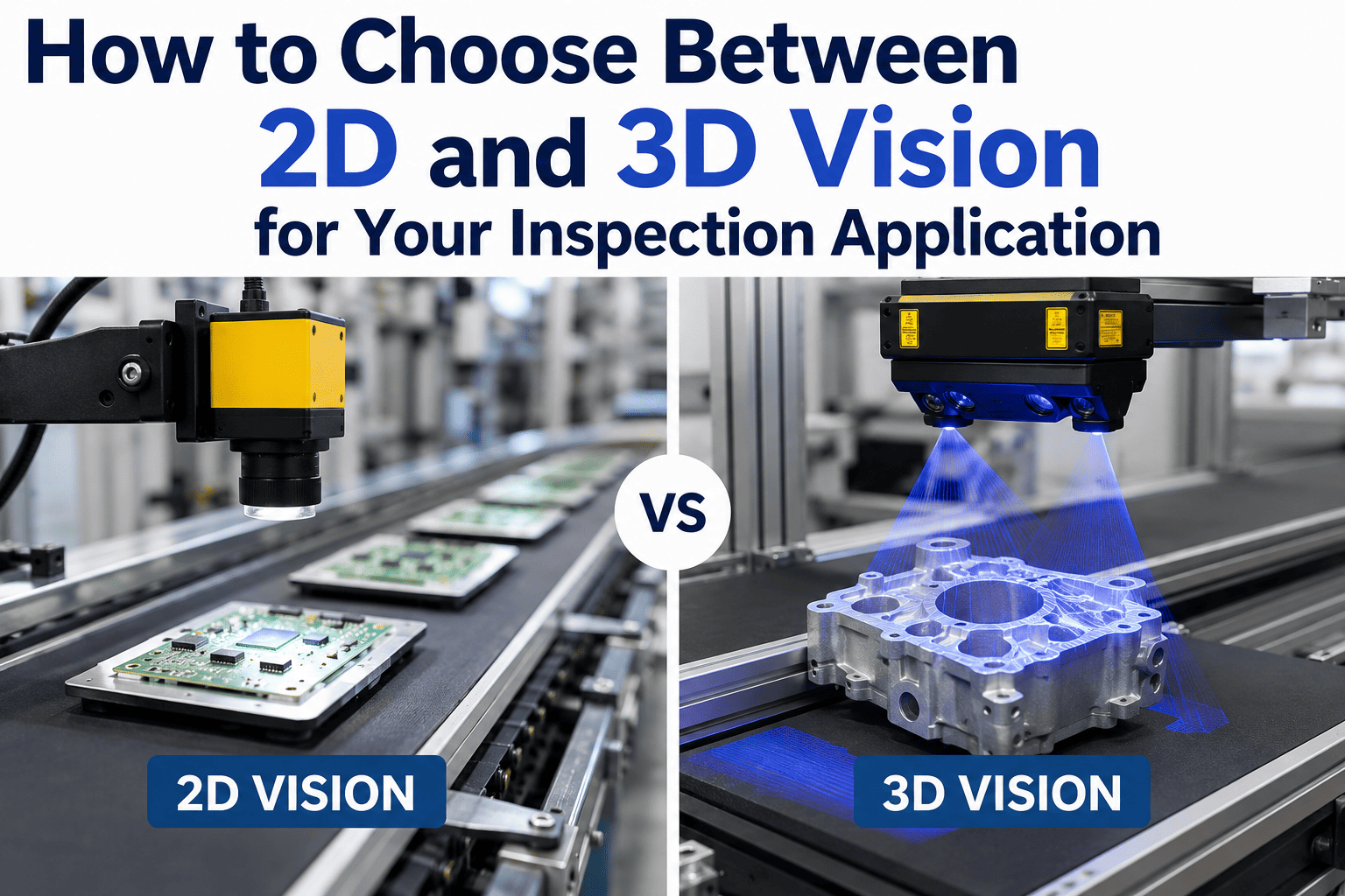
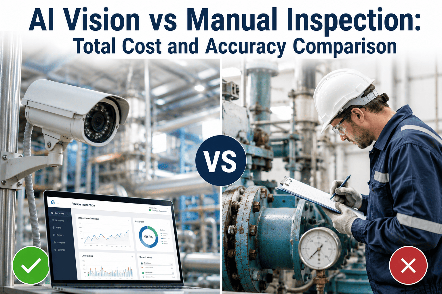
A 2D camera and a laser scanner are often quoted against each other on the same purchase order, but they answer different questions about a part and produce fundamentally different data. A 2D vision system captures what the surface looks like — pixels of color, contrast, texture, and edge — and lets a trained model decide whether that appearance matches an acceptable reference. A laser scanner captures where the surface actually is in three-dimensional space, producing a point cloud of measured coordinates that can be compared against a CAD model to the tolerance the metrology hardware supports. Neither is a strict substitute for the other, and the buyer who understands where each one's strength ends is the one who deploys the right technology at the right station — iFactory's deployment engineering team helps quality leaders make exactly that call before capital gets committed.
Buyer Guide · Measurement Technology Comparison
AI Vision vs Laser Scanning: Choosing Between 2D Vision and 3D Point Clouds
2D vision reads appearance. Laser scanning reads geometry. The question isn't which one wins on paper — it's which one is physically capable of answering the question your quality team is actually trying to answer, and where the two technologies belong alongside each other on a production line.
Two Technologies, Two Completely Different Data Types
The most useful way to compare AI vision against laser scanning is to look at what each one actually produces as its output. A 2D vision system delivers an image — a two-dimensional grid of pixel values that a model interprets to make a decision about the part. Every conclusion the system reaches, whether it's identifying a scratch on a painted surface or checking whether a label is present, comes from analyzing that grid of pixels. There is no measured Z-axis in the raw data, which means depth information has to be inferred from shading, shadow, or perspective rather than measured directly.
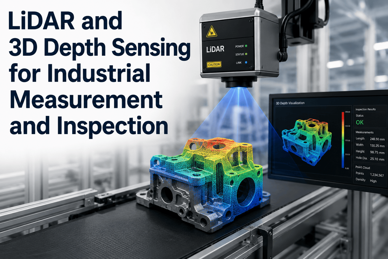
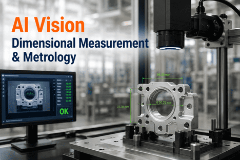
A laser scanner delivers a point cloud — a set of three-dimensional coordinates that describe where the surface of the part is in physical space, measured directly against the scanner's calibrated reference frame. Every point in that cloud is a metrology-grade measurement, not an interpretation. Compare a point cloud against the part's CAD model and you get a dimensional deviation map that shows exactly where the physical part differs from its designed geometry, down to the resolution the scanner is calibrated to.
This distinction matters because it determines what questions each modality can answer. Ask a 2D vision system to measure whether a machined feature is 0.05 millimeters above its designed height, and it will struggle unless the height difference happens to change the surface appearance in a way the camera can see. Ask a laser scanner to identify a subtle color shift or a printing defect, and it will return nothing meaningful because color is not what a laser scanner measures. The right technology is the one whose native data type matches the question you're asking, and mismatched deployments are how quality programs end up with expensive inspection stations that can't catch the defects they were bought to catch.
How the Data Gets Captured
2D Image Capture vs 3D Point Cloud Acquisition
The camera captures a rich, high-resolution representation of what the surface looks like, but the depth axis is missing from the data. The laser scanner captures fewer bytes of information about each point on the surface, but every one of those bytes is a calibrated measurement in three dimensions. This is why a scan of a part can be compared numerically against a CAD file, while a photograph of the same part cannot — the point cloud lives in the same coordinate space as the design intent, and the photograph does not.
Native Strengths of Each Modality
What Each Technology Is Built to Do Best
Every inspection technology has a small set of tasks it was fundamentally designed for, and a much larger set of tasks where it can be forced to work with enough engineering effort but rarely wins on total cost or reliability. Starting from the native strengths of each modality is the fastest way to arrive at a deployment plan that doesn't fight the physics.
2D AI Vision
Reads appearance at line speed
Surface Defect Detection
Scratches, dents, stains, discoloration, and cosmetic blemishes — anything that changes how the surface reflects light — are what 2D vision was built to catch.
Color and Texture Analysis
Dye lot consistency, coating uniformity, wood grain matching, and printed pattern verification live entirely in the pixel domain where 2D cameras excel.
Presence and Orientation
Component present or absent, label right-side up, cap seated, seal intact — high-speed pass or fail checks at full line takt time.
2D Dimensional Gauging
Length, width, hole diameter, and edge-to-edge distances on features that lie in a single plane, measured to sub-pixel precision on calibrated systems.
Character and Code Reading
OCR, OCV, barcodes, data matrix codes, and serial number verification — reading marks the camera can see and validating them against expected values.
vs
Laser Scanning
Measures geometry against CAD
3D Dimensional Verification
Height, depth, step, undercut, and any other measurement that requires resolving the Z-axis — the native output of a calibrated laser scan.
CAD-to-Part Comparison
Color-mapped deviation showing exactly where the physical part differs from its designed geometry, feature by feature, in the tolerance units the drawing specifies.
Surface Profile Analysis
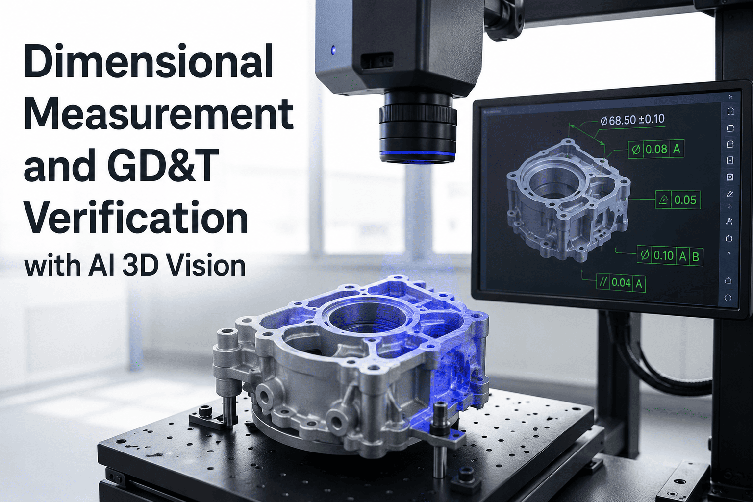
Flatness, straightness, cylindricity, and other geometric dimensioning and tolerancing callouts that require full-surface geometric evaluation.
Volume and Warpage
Fill volume in shaped containers, sheet metal springback, injection-molded part warpage — measurements that need actual 3D geometry, not projected appearance.
Reverse Engineering Support
Capturing a physical part into a digital model that can be compared, archived, or fed back into design revision — a workflow that has no 2D equivalent.
Right Tool, Right Station
Stop Fighting the Physics of Your Inspection Technology
iFactory's platform runs 2D AI vision at line speed on every part and integrates cleanly with laser scanner data for the 3D dimensional questions vision cannot answer. That combination is what a mature quality program actually looks like on a shop floor.
Vendor specification sheets rarely put the two technologies on the same axes, which makes side-by-side comparison harder than it should be. The table below covers the dimensions that shape a real purchase decision — not the marketing numbers, but the ones that determine whether the technology can do what you need it to do on your specific part.
Specification
2D AI Vision
Laser Scanning
Data type
2D pixel image
3D point cloud with XYZ coordinates
Native measurement
Length, area, angle in 2D plane
Height, depth, volume, full 3D geometry
Typical resolution
Sub-pixel with calibration
Micron-level on calibrated systems
Inspection speed
Milliseconds per part, full line takt
Seconds per part, sweep or scan cycle
Best for surfaces that are
Matte, textured, printed, colored
Solid, non-reflective, non-transparent
Challenges
Depth ambiguity, lighting sensitivity
Shiny surfaces, dark colors, translucency
CAD comparison
Requires additional projection logic
Native deviation map against CAD file
Capital cost
Lower — camera, lighting, compute
Higher — precision optics, motion stage
Coverage on line
100% of parts at production speed
Sampled or gated on critical stations
Model training
Deep learning models, active retraining
Rule-based against CAD reference
The row worth highlighting is best-fit surface behavior. Laser scanners have known difficulty with shiny, dark, and translucent surfaces because those surface types either reflect the laser away from the sensor, absorb it, or let it pass through — all three break the assumption that the returned beam represents the physical surface location. 2D vision handles those surfaces with appropriate lighting design but struggles the other way, with depth ambiguity on features that look flat in an image but have real 3D relief. Matching the technology to your part's surface behavior is often what determines whether either system will work at all.
Scenario-Based Selection
Which Modality Wins in Which Scenario
Rather than argue in the abstract, it's easier to walk through the scenarios where the answer is clear-cut and see the pattern. The following situations come up on almost every production floor and each has a natural technology choice.
1
Painted Body Panel Inspection
2D AI Vision
The defects that matter — orange peel, sags, contamination, color mismatch — are appearance defects that live entirely in the pixel domain. A laser scan of a painted panel gives you a beautifully accurate surface geometry that tells you nothing about whether the paint looks right.
2
Machined Aluminum Housing Height Check
Laser Scanning
Verifying that a machined boss stands 12.5 millimeters above its base to a tolerance of 0.02 millimeters is a Z-axis measurement problem. A calibrated laser scanner answers this directly against the CAD file; a 2D camera can only infer height from indirect signals like shadow or perspective distortion.
3
Printed Label and Barcode Verification
2D AI Vision
Reading a printed code, verifying it matches the expected value, and checking print quality against a reference are purely pixel-domain tasks at line speed. A laser scanner would return a flat surface with no readable content because the print does not create measurable geometric relief.
4
Injection Molded Part Warpage
Laser Scanning
Warpage is a 3D deformation measured against the designed part shape. Only a scan against the CAD file resolves how the physical part deviates from nominal geometry across its full surface. A camera cannot see warpage unless it's severe enough to disturb the surface appearance.
5
Assembly Presence and Orientation
2D AI Vision
Confirming that all fasteners are installed, that a connector is oriented correctly, and that no components are missing is a high-speed appearance check on every unit. Laser scanning is overkill for a task that doesn't require dimensional measurement.
6
Sheet Metal Flatness Verification
Laser Scanning
Flatness is a geometric callout defined against a reference plane in three dimensions. Laser scanning captures the full surface elevation map that a flatness evaluation requires. A 2D camera can hint at flatness through shading but cannot deliver the numeric deviation a quality report needs.
The pattern across these scenarios is consistent: appearance-driven checks belong to 2D vision, geometry-driven checks belong to laser scanning, and any attempt to force the wrong modality onto the wrong problem produces a station that either barely works or fails the moment part variation exceeds what the compromise architecture was tuned for.
The Combined Deployment
Why Serious Quality Programs Deploy Both Together
The most sophisticated inspection strategies stop treating this as a choice and start treating it as a layout question. 2D vision handles the volume — every part, every second, every appearance-related defect class — and laser scanning handles the dimensional gates where 3D geometry actually matters. The two feed a single quality record so each part's inspection history is coherent rather than fragmented across disconnected systems.
Stage A
Inline 2D Vision — Every Part
A camera-based station runs at line speed on 100% of parts, catching surface defects, verifying component presence, and reading identification codes as they pass through. This is the coverage layer, the wide net that makes sure nothing that looks wrong ships without being flagged.
→
Stage B
Gated Laser Scan — Critical Stations
Laser scanning sits at the dimensional checkpoints — after machining, before assembly, at final acceptance — where a 3D measurement against CAD is what quality actually requires. This is the precision layer, deployed where its slower cycle is justified by the consequence of a geometric defect escaping.
→
Stage C
Unified Quality Record
Vision measurements and scan results both write against the same part serial number in a single traceability database. A customer audit or a warranty investigation can pull the complete inspection history of any unit — appearance and geometry both — without stitching data from two disconnected silos.
This layered approach costs less over the equipment's life than either single-modality deployment because it stops trying to force one technology to do the other's job. 2D vision doesn't get overloaded with brittle 3D measurement logic it was never designed for; laser scanning doesn't waste cycle time on parts where a fast pass-fail appearance check would have been enough. Each technology operates in its native domain, and the quality data lands in one place where it can actually be used.
Coverage Plus Precision
See the Layout That Combines Vision Coverage With Scan Precision
iFactory's platform is designed to run 2D AI vision continuously on every part while integrating laser scanner records into the same part-level quality database. That's what a working two-modality strategy looks like when the data actually lives together.
The Mistakes That Turn Good Technology Into Wasted Capital
Most inspection technology failures aren't about the hardware itself. They're about deployment decisions made before the equipment arrived, when the wrong modality got assigned to the wrong problem or when integration was treated as an afterthought. The pitfalls below are the ones that show up most often on quality reviews of stations that never delivered what they were supposed to.
Buying 3D Because It Sounds Better
A laser scanner is not automatically superior to a 2D camera — it's a different tool. Deploying laser scanning on a station that only needs presence detection or label verification wastes cycle time and capital on measurements you don't use, while producing worse coverage than a fast 2D system would have delivered.
Forcing 2D to Solve a 3D Problem
Trying to measure part height, depth, or warpage from a single-camera 2D image using shadow tricks or stereo approximation almost always ends with a system that works on tuned parts and fails when real production variation shows up. If the measurement needs Z-axis data, use hardware that measures Z-axis directly.
Ignoring Surface Behavior
Laser scanners struggle on shiny, dark, and translucent surfaces. 2D vision struggles on low-contrast features. A pilot that succeeds on ideal reference parts can fail on the actual production mix if the surface behavior of real parts wasn't part of the modality selection conversation.
Siloing the Inspection Data
Vision results in one database, scan results in another, and no traceability layer that ties them to the same part serial number. This is the most common integration failure and the one that quietly costs the most, because it turns two working inspection stations into two disconnected quality records that no one can query as a single history.
Skipping the Defect Inventory
Choosing a modality without first cataloging the failure modes the inspection is meant to catch is how plants end up with expensive equipment that catches the wrong defects. The decision should start with the defect list, not with the technology sales pitch.
Under-Budgeting Retraining and Recalibration
Vision models drift as products and lighting change; laser scanners drift as thermal conditions and mechanical stages age. Both need periodic maintenance to keep delivering their specified performance, and a deployment that budgets only for purchase price rarely holds up beyond the first product revision.
Field Perspective
"
The clearest signal that a plant hasn't thought carefully about this comparison is when I see a laser scanner running on a station where the only quality question is whether a component is present. That's a 2D vision problem, and a scanner running there is throwing away cycle time on a measurement no one uses. The opposite mistake is even more expensive though — a 2D vision system tuned within an inch of its life to try to measure part warpage from a single camera angle, and shipping bad parts every time the production mix shifts because the depth inference was never physically reliable to begin with. My rule after a couple of decades on this: if the acceptance criterion has a Z-value in it, use hardware that measures Z. If it has a color, texture, or presence word in it, use a camera. And run both data streams into the same quality record — the second you have vision measurements in one system and scan results in another, you've built two inspection stations that can't answer a single question about a single serial number.
Marcus Van Der Berg
Metrology Systems Architect · 22 years in automotive powertrain and precision machining inspection
Common Questions
Frequently Asked Questions
Can 2D AI vision extract 3D information from a single image?
To a limited degree, yes — modern deep learning models can infer approximate depth from shading, texture gradients, and known reference geometry in an image, and multi-camera stereo setups can reconstruct depth from two synchronized views. But inferred depth from a 2D system is not the same as measured depth from a calibrated 3D scanner. When your acceptance criterion is a dimensional tolerance in the drawing, inferred depth is rarely accurate enough to certify the part; when you just need to know a feature is present and roughly positioned, inferred depth is usually more than sufficient. Talk to deployment engineering about whether your specific measurement needs true 3D or inferred depth.
Are laser scanners safe to use around production operators?
Industrial laser scanners used for dimensional measurement typically operate in the visible or near-infrared spectrum at power levels classified as Class 2 or Class 3R under standard laser safety classifications, which are generally safe under normal use conditions but require operators to avoid direct beam exposure. Higher-power scanning systems require additional safety enclosures and operator training. The overall safety profile is well-understood and standard PPE practices cover the vast majority of industrial deployments, though the specific safety plan should be reviewed against the exact system being installed.
Which technology has better return on investment for a mid-volume production line?
There is no universal answer because ROI depends entirely on what defect classes are driving your scrap and warranty costs. If most of your escaping defects are appearance-related — surface finish, missing components, print quality — 2D vision typically delivers ROI faster because it can run on 100% of parts at line speed with lower capital and operating cost per unit inspected. If your escaping defects are dimensional and safety-critical, laser scanning delivers ROI even at sampled coverage because a single caught geometric defect can offset the equipment's cost. Book a demo to walk through the ROI math on your specific defect mix.
How do I handle shiny or dark surfaces that laser scanners struggle with?
Several practical approaches address the reflective surface challenge. Some laser scanners use blue laser wavelengths that perform better on shiny and dark surfaces than the red lasers commonly used in older systems. Anti-reflective spray coatings are applied to parts before scanning in metrology labs, though this is impractical on a production line. Structured light scanners often outperform single-line laser scanners on difficult surfaces because they capture a full pattern rather than a single reflected line. Where the surface is genuinely uncooperative, the pragmatic answer is often to use 2D vision for that inspection and reserve laser scanning for parts and features with cooperative surface behavior.
Can vision and scan data be combined into a single quality report per part?
Yes, and it is one of the highest-value integrations a quality program can build. When 2D vision measurements and 3D scan results are both linked to the same part serial number in a single quality database, a customer audit or warranty investigation can pull the complete inspection history of any unit — appearance defects, dimensional measurements, and any deviations flagged at either station — from one query. This unified record turns two separate inspection stations into a single coherent quality picture, which is what mature quality programs work toward regardless of which modalities they ultimately deploy.
Right Data, Right Question, Right Station
See How iFactory's AI Vision Fits Into Your 2D and 3D Inspection Strategy
Every mature quality program eventually pairs 2D vision with 3D scanning because no single data type can answer every quality question. iFactory's platform handles the appearance, geometry, and assembly inspection that lives in the pixel domain — and integrates with the scan data your dimensional stations produce so the full quality history lands in one place.