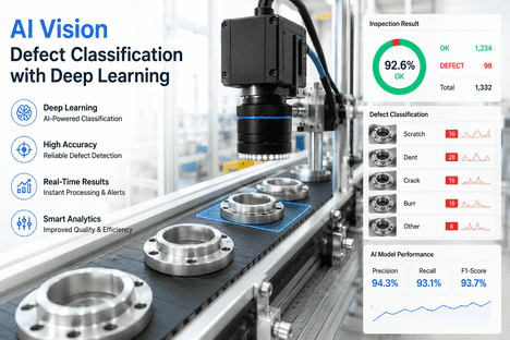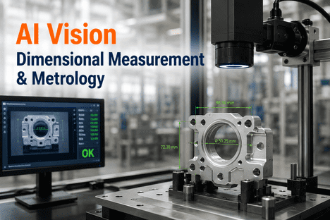
Dimensional measurement and geometric verification at production speed is one of the most consequential unsolved problems in industrial quality control. Every manufactured component has a dimensional specification — a diameter, a length, a flatness tolerance, a hole position relative to a datum — and every dimensional non-conformance that reaches the next assembly stage or the customer creates a failure consequence whose cost grows exponentially as it travels further down the value chain. A shaft 0.05 mm oversize that passes a go/no-go gauge check but violates a true-position tolerance creates a bearing fit failure in the field. A formed bracket that meets its individual feature dimensions but fails a flatness specification causes a misalignment in the assembly it supports. These are the failure modes that statistical sampling inspection cannot reliably catch and that manual coordinate measuring machine programs cannot address at production throughput rates. Traditional dimensional verification — manual gauge checks, periodic CMM sampling, functional gauging at end-of-line — addresses a fraction of the inspection requirement with latency measured in hours or shifts. AI vision dimensional measurement and metrology replaces this periodic, sample-based model with 100% in-line geometric inspection at production speed — delivering tolerance verification against design intent for every part, every cycle, without contact, without cycle time impact, and with structured dimensional data that feeds directly into SPC, process feedback, and quality record systems. iFactory's AI vision camera platform with vision measurement capability provides non-contact dimensional inspection at ±0.01 mm measurement uncertainty on production lines across automotive, aerospace, pharmaceutical, electronics, and precision engineering manufacturing — giving quality and process engineers the real-time dimensional intelligence that manual gauging programs cannot generate at the frequency and completeness that modern process control requires. Quality engineers and metrology specialists evaluating their current dimensional inspection architecture regularly choose to Book a Demo with iFactory's engineering team to see how AI vision measurement maps to their specific feature types, tolerance requirements, and production throughput.
Why Traditional Dimensional Inspection Cannot Meet Modern Quality Requirements
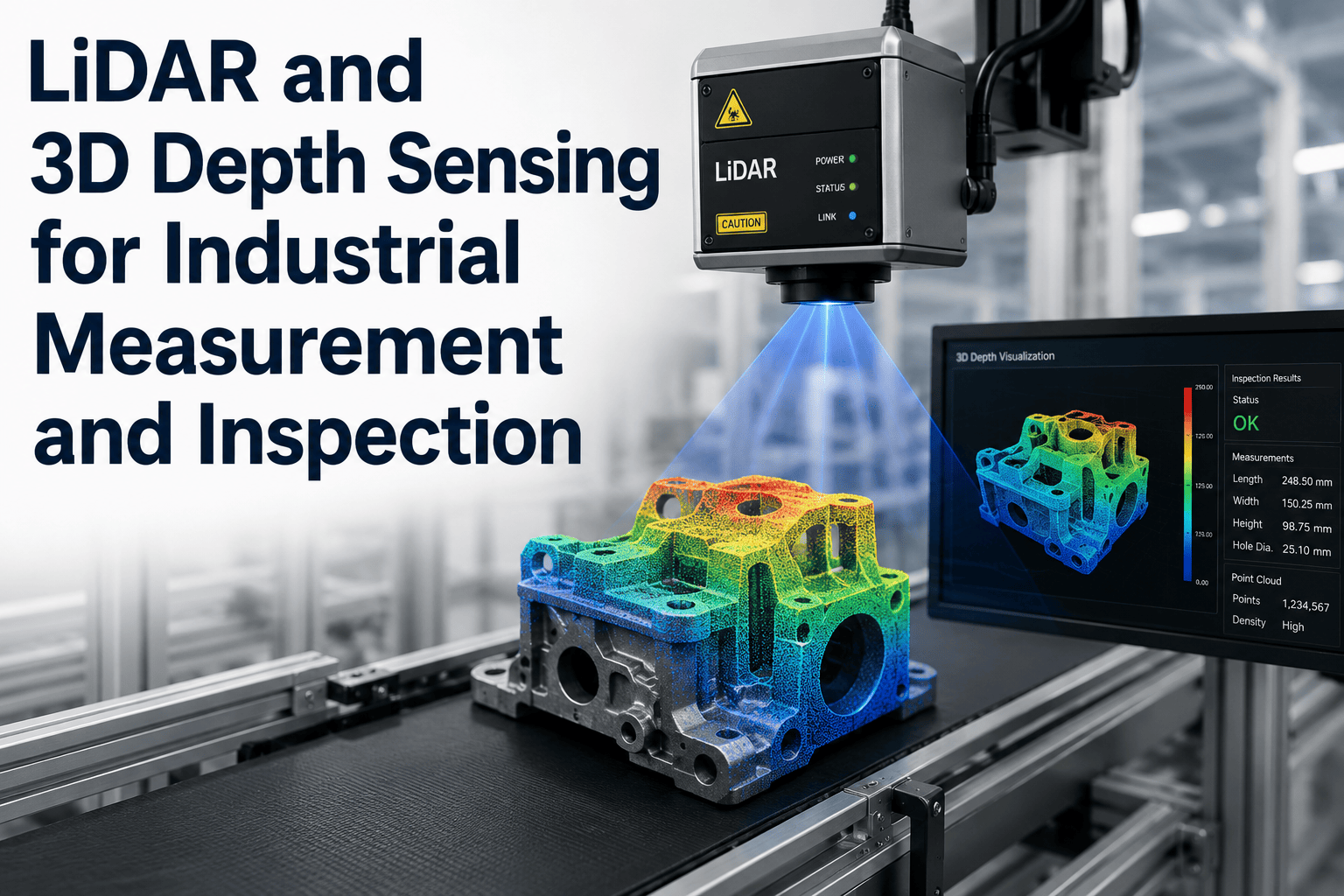
The inspection interval problem in dimensional quality control is structural and widely underestimated. Most manufacturing facilities inspect dimensional compliance on a sampling basis — periodic CMM measurements at frequencies of one to five parts per hour, manual gauge checks at start-of-shift and after tool changes, functional gauging that verifies assembly fit without measuring the underlying dimensional cause. This sampling model was designed when measurement was slow and expensive; it persists because the alternative — full-population measurement — required contact-based metrology equipment that could not operate at production throughput rates without dedicated measurement cells and significant cycle time impact. AI vision dimensional measurement changes this constraint entirely. Non-contact measurement using structured light, photogrammetric imaging, and telecentric optics operates at camera frame rates — measuring every part in the production flow without interrupting the production cycle, without contact that could mark precision surfaces, and without the measurement cell throughput limitation that makes 100% CMM inspection economically impractical. The result is a dimensional inspection coverage model that was previously impossible: full-population dimensional data, in real time, for every part produced, with uncertainty specifications that satisfy GR&R requirements for the tolerance ranges of most production features. iFactory's AI vision camera platform implements this model across the precision range from ±0.01 mm for tight-tolerance aerospace and medical device features to ±0.1 mm for larger structural components — covering the dimensional inspection requirements of the majority of manufactured parts without contact, without sampling, and without cycle time impact.
Dimensional Feature Types and Geometric Characteristics Measured by AI Vision
Effective AI vision dimensional measurement requires imaging and measurement configurations matched to the specific feature type, tolerance requirement, and part geometry being inspected. The measurement capability of the system is determined by the combination of optical configuration — telecentric versus perspective optics, structured light versus photogrammetric imaging, 2D area scan versus 3D point cloud acquisition — and the measurement algorithm applied to the captured data. iFactory's platform supports the full range of dimensional and geometric characteristic measurement types required by GD&T-specified production parts across manufacturing industries.
Linear Dimensions — Length, Width, Height, and Diameter
Linear feature measurement using telecentric lens optics with pixel-level edge detection provides length, width, height, and diameter measurements at sub-pixel accuracy. Telecentric optics eliminate the perspective projection errors that affect dimensional accuracy in standard camera configurations — ensuring that feature dimensions are measured correctly regardless of part position variation within the field of view. Measurement repeatability for linear features at typical production part scales (1–500 mm) achieves ±0.01–0.05 mm depending on feature size and optical configuration — satisfying GR&R requirements for tolerance ranges down to 0.1 mm on parts of this scale. Thread pitch and major diameter, shaft diameter, bore diameter, and formed feature dimensions including bend angles and radii are measurable within this linear measurement framework using appropriate illumination geometries.
Geometric Tolerances — Flatness, Roundness, Straightness, and Cylindricity
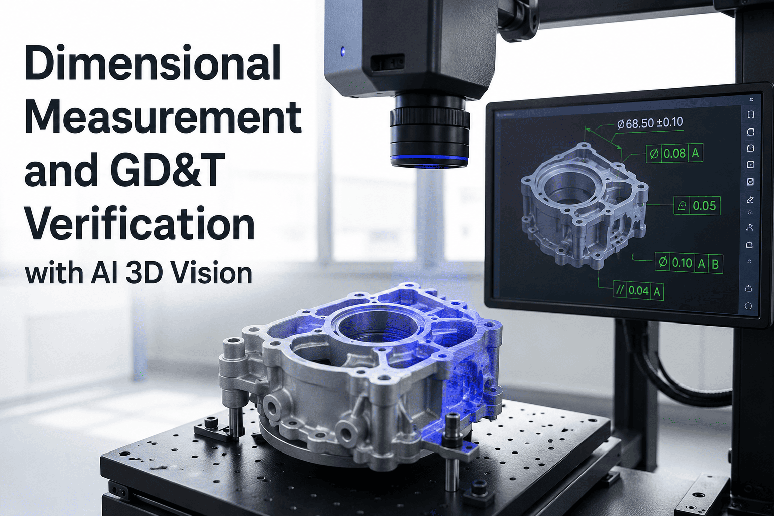
Geometric form tolerances require measurement of feature shape deviation from the ideal geometric form — the variation of a flat surface from true flatness, a circular cross-section from true roundness, or a cylindrical axis from true straightness. AI vision measurement of these characteristics uses 3D structured light imaging that captures the full surface geometry of the measured feature as a point cloud, from which form deviation is computed using least-squares fitting algorithms consistent with ISO 1101 geometric tolerancing standards. Flatness measurement is particularly valuable for sealing surfaces, mounting faces, and precision mating interfaces where assembly performance depends on surface form as much as dimensional position. Roundness and cylindricity measurement provides in-line monitoring of turning and grinding process quality without requiring CMM access or manual roundness gauge setup.
Position and Location Tolerances — True Position, Coaxiality, and Symmetry
Location tolerances — true position, coaxiality, concentricity, and symmetry — specify the permitted variation in the location of a feature relative to a datum reference frame. These are among the most consequential dimensional requirements in precision manufactured parts because location errors that exceed position tolerances cause assembly interference, misalignment, and functional failure even when all individual feature dimensions are within their own tolerance specifications. AI vision measurement of position tolerances uses multi-datum registration — identifying the datum features of the part in the field of view and computing the location of the measured feature relative to the registered datum frame — providing the true-position measurement that functional gauging cannot deliver and CMM sampling cannot provide at production frequency. This capability is particularly valuable for hole patterns, threaded insert locations, and press-fit bore positions in precision assemblies. Pharmaceutical manufacturers evaluating blister cavity position accuracy and electronics manufacturers verifying component pad location on PCBs benefit from the same position measurement capability applied to their specific feature scales and tolerance requirements. Teams wanting to see position measurement demonstrated on features matching their specific GD&T requirements can Book a Demo with iFactory's metrology engineering specialists.
Profile and Surface Form — Profile of a Line and Profile of a Surface
Profile tolerances control the deviation of a surface or line element from its nominal form — applicable to freeform surfaces, contoured features, and complex geometry that cannot be fully characterised by simple linear or geometric tolerance specifications. AI vision 3D imaging captures full surface profiles of complex features as dense point clouds that are compared against CAD-derived nominal surface models using best-fit alignment and deviation mapping algorithms. Applications include aerofoil and turbine blade profile inspection, automotive body panel gap and flush measurement, formed sheet metal profile compliance verification, and lens and optical component surface form inspection — all geometric inspection requirements where contact probing is either impractical or too slow for 100% production inspection. The deviation map output — showing where and by how much the actual surface deviates from nominal — provides the spatial context for process adjustment and tooling correction that simple pass/fail gauging cannot deliver.
Assembly Verification — Gap, Flush, and Mating Feature Confirmation
Assembly dimensional verification extends the measurement scope from individual component features to the dimensional characteristics of assembled products — the gap between mating panels, the flush alignment of adjacent surfaces, the seating depth of press-fit components, and the engagement length of threaded connections. These assembly-level dimensional characteristics are not inspectable on individual components before assembly and require measurement of the assembled product either destructively or using in-line dimensional imaging of the assembled unit. AI vision assembly verification uses the same non-contact imaging architecture applied to component measurement — operating on the assembled product in the production line, within the production cycle time, providing assembly-level dimensional confirmation that the production process has successfully brought components together within specification.
AI Vision Measurement vs. Traditional Dimensional Inspection Methods
The operational case for AI vision dimensional measurement is built on the performance gap between what traditional methods can deliver and what modern quality systems require. Understanding this gap across the primary inspection method categories clarifies where AI vision measurement adds the most value in each manufacturing environment.
| Inspection Method | Coverage | Throughput | Data Output | iFactory AI Vision Advantage |
|---|---|---|---|---|
| Manual Gauge Check | Sampled — 1–5 per hour | Limited by operator speed | Pass/fail — no measurement value | 100% coverage, real measurement value, no operator variability |
| Coordinate Measuring Machine (CMM) | Sampled — offline, periodic | 1–10 parts per hour typical | Full dimensional report — off-line, lagged | In-line, 100% coverage, real-time SPC at CMM-equivalent uncertainty |
| Functional / Attribute Gauging | 100% — go/no-go only | High — but no measurement data | Pass/fail only — no process feedback | Quantified dimensional values for every part, SPC trend data |
| Contact Probing In-Line | 100% — selected features | Cycle time addition per part | Feature values — limited feature set | Non-contact, no cycle time impact, full surface coverage possible |
| Manual Vision / Optical Comparator | Sampled — operator-dependent | Low — high operator effort | Variable — operator judgement | Automated, repeatable, 100% coverage, quantified output |
| iFactory AI Vision Measurement | 100% — all parts, all features in scope | Production line speed — no impact | Full dimensional values, SPC, trend alerts | Best-in-class across coverage, throughput, and data completeness |
Industry Applications: Where AI Vision Dimensional Measurement Delivers Highest Return
The value of AI vision dimensional measurement varies by industry based on the combination of tolerance tightness, part throughput, defect consequence, and the existing inspection method being replaced. The following application profiles reflect the highest-ROI deployment scenarios across the industries iFactory's platform serves.
In-Line Gauging for Powertrain and Chassis Features
Automotive powertrain components — camshafts, crankshafts, connecting rods, gear blanks, and bearing housings — require dimensional verification of critical features at high production rates where 100% CMM inspection is economically impractical. AI vision in-line gauging provides diameter, length, and position measurements at cycle rates matching the machining cell throughput, feeding SPC data in real time to the process control system. Dimensional trend alerts enable automatic tool offset corrections that maintain the process within tolerance without manual intervention — reducing scrap from tool wear events and eliminating the inspection lag that allows tool-wear-related dimensional drift to produce multiple non-conforming parts before detection.
GD&T Feature Verification and First-Article Documentation
Aerospace precision components carry GD&T specifications that require position and profile tolerance verification at frequencies that periodic CMM sampling cannot provide. AI vision 3D measurement provides position, profile, and form data for in-process verification at production rate, supplementing rather than replacing periodic CMM confirmation. For first-article inspection, iFactory's platform generates dimensional measurement reports with feature-by-feature tolerance comparison against the nominal CAD model in the format required by AS9100 Rev D Clause 8.5.1.1 and customer-specific FAI requirements — reducing the elapsed time for first-article documentation from days to hours while providing full-population measurement data for the FAI lot. Book a Demo to review iFactory's aerospace dimensional measurement and FAI documentation capability.
Blister Cavity Dimensions and Container Geometry
Pharmaceutical packaging dimensional verification covers blister cavity depth and width compliance, container wall thickness uniformity, closure thread geometry, and fill level measurement — each of which affects product integrity, dose accuracy, or regulatory compliance. AI vision measurement provides 100% dimensional verification of these features at packaging line speed, feeding dimensional data directly to the batch record and triggering rejects before dimensionally non-conforming packaging units advance to the filling station. The combination of dimensional verification and defect detection in the same vision platform eliminates redundant inspection stations and generates the unified packaging quality record that cGMP batch record requirements specify.
Component Placement Accuracy and PCB Feature Measurement
Electronics manufacturing dimensional verification covers component placement offset from pad centre, component polarity orientation, solder ball height and diameter uniformity, PCB trace width and spacing, and connector pin height and coplanarity — features measured in the 0.01–1 mm scale range that requires high-resolution imaging at production throughput rates that contact probing cannot approach. AI vision measurement with telecentric optics and sub-pixel edge detection provides the measurement resolution and repeatability required for these feature scales, with output data structured for SPC monitoring of placement accuracy trends and integration with automated optical inspection (AOI) systems for combined dimensional and defect inspection in a single pass.
Critical Dimension Verification for Implants and Instruments
Medical device dimensional verification addresses critical features whose deviation from specification creates patient safety risk — implant stem diameter for press-fit engagement, instrument tip geometry for surgical function, and catheter and tube outer diameter for catheter-over-wire compatibility. ISO 13485 quality management systems require documented evidence of dimensional compliance for these features on every device lot released to distribution. AI vision measurement generates this evidence automatically as a byproduct of production inspection — providing the per-lot dimensional data and device history record entries that ISO 13485 and FDA 21 CFR Part 820 require without the manual measurement and record entry overhead that CMM-based dimensional sampling programs impose on production planning.
Formed Feature Verification and Assembly Fit Confirmation
Precision engineering and metal fabrication dimensional inspection covers formed sheet metal angle and radius compliance, weld bead geometry verification, machined surface dimensional and flatness compliance, and assembled component gap and flush confirmation. These inspection requirements span a wide tolerance range — from tight-tolerance machined features at ±0.05 mm to formed sheet metal features at ±0.5 mm — and benefit from AI vision measurement configurations that match the measurement uncertainty requirement to the feature tolerance range rather than applying the highest-precision configuration universally. iFactory's configurable measurement architecture deploys the appropriate optical configuration and measurement algorithm for each feature type and tolerance requirement within the same inspection platform.
Real-Time SPC Integration and Process Feedback
The full value of AI vision dimensional measurement is realised when the dimensional data it generates feeds back into the process that created the measured features — not just into the quality record for the parts already produced. Real-time SPC integration converts the stream of per-part dimensional measurements from a historical quality record into a live process monitoring signal that enables intervention before the process drifts outside tolerance rather than after non-conforming parts have already been produced.
iFactory's dimensional measurement platform outputs structured per-part measurement data to SPC software via OPC-UA and REST API in real time, at the measurement cycle rate. SPC software calculates Xbar-R and individual-moving-range control charts, Cpk and Ppk capability indices, and trend alerts for out-of-control conditions using Western Electric and Nelson rules. When a dimensional trend alert fires — indicating that the measured feature is approaching its control limit before it reaches the specification limit — the platform routes the alert simultaneously to the operator HMI, the CMMS for process check work order generation, and the machine tool CNC controller for automated tool offset correction where the machining cell supports closed-loop feedback. This architecture converts AI vision dimensional measurement from a quality gate that catches non-conforming parts into a process intelligence system that prevents them from being produced — the distinction between reactive quality control and proactive process management that modern manufacturing operations require. Teams ready to see this closed-loop architecture demonstrated on their specific process and dimensional feature combination can Book a Demo with iFactory's process integration specialists.
Measurement System Analysis and GR&R Qualification
Before an AI vision dimensional measurement system can be used as a quality control decision tool, it must be qualified as a measurement system through gauge repeatability and reproducibility (GR&R) analysis — demonstrating that the measurement system's variation is small relative to the tolerance it is measuring and that measurement results are consistent across operators and over time. This qualification requirement applies to AI vision measurement systems under the same framework that governs manual and CMM-based measurement systems in IATF 16949, ISO 13485, AS9100, and FDA-regulated quality systems. iFactory's measurement platform is designed for GR&R qualification from the outset — with stable optics and illumination configurations, deterministic measurement algorithms that eliminate the operator-judgement variability component from the GR&R study, and calibration architecture that uses traceable reference standards for uncertainty chain traceability. GR&R study results for iFactory's configurations consistently demonstrate measurement system variation below 10% of the tolerance for the feature types and measurement ranges within the system's specified capability — qualifying for use as a statistical process control measurement source under MSA criteria. Qualification documentation in the format required by IATF 16949 MSA study reporting, ISO 13485 measurement system validation, and AS9100 calibration record requirements is generated automatically from the GR&R study data without manual report preparation. Customers preparing measurement system validation documentation for their quality management system or for regulatory submission can review iFactory's qualification documentation framework by scheduling a Book a Demo session with iFactory's metrology engineering team.
Frequently Asked Questions: AI Vision Dimensional Measurement and Metrology
What measurement uncertainty is achievable with AI vision dimensional measurement, and how does it compare to CMM?
Achievable measurement uncertainty depends on the optical configuration, feature scale, and environmental conditions of the specific deployment. For telecentric optic configurations on features in the 1–200 mm scale range, AI vision measurement achieves ±0.01–0.05 mm measurement uncertainty — comparable to contact probing CMM performance for the same feature types when appropriate calibration and environmental controls are applied. For larger-scale features and formed components in the 200–1000 mm range, uncertainty ranges from ±0.05–0.2 mm depending on the imaging configuration. These values satisfy GR&R requirements for tolerance classes down to 0.1 mm, covering the majority of production machined and formed features in precision manufacturing. For ultra-tight tolerance applications below ±0.01 mm measurement uncertainty, the combination of AI vision for 100% screening and CMM for confirmation sampling on flagged parts provides the most cost-effective inspection architecture rather than attempting to achieve sub-0.01 mm vision measurement on 100% of parts.
Can AI vision dimensional measurement replace CMM inspection entirely, or does it supplement it?
For most production dimensional inspection applications, AI vision measurement most effectively supplements rather than replaces CMM — with each method deployed in its area of comparative advantage. AI vision excels at 100% in-line screening of the critical features that define production conformance and drive SPC monitoring — providing the full-population data that sampling-based CMM inspection cannot generate. CMM excels at complex geometric feature measurement, measurement of features requiring part repositioning, and first-article comprehensive dimensional reporting that covers every specified feature in the design model. The highest-performing inspection programs deploy AI vision measurement for 100% in-line coverage of the highest-frequency, highest-consequence features, and CMM for periodic confirmation measurement of the full feature set and for non-conformance investigation when AI vision alerts identify a dimensional problem requiring root cause analysis. This combined architecture delivers better quality protection than either method alone at lower total cost than 100% CMM inspection would require.
How does the platform handle dimensional measurement on reflective, transparent, or dark-coloured parts?
Reflective, transparent, and dark-coloured surfaces present distinct imaging challenges that AI vision measurement addresses through illumination configuration selection matched to the surface material. Highly reflective metal surfaces — polished stainless steel, chrome plating, aluminium alloy — use polarised illumination configurations that suppress specular reflection, enabling edge detection and surface imaging without the saturation artefacts that direct illumination creates on these surfaces. Transparent materials — glass, acrylic, pharmaceutical packaging films — use grazing or coaxial illumination that creates contrast at the material boundary through refraction or edge enhancement rather than surface reflection. Dark-coloured surfaces use bright-field structured illumination at higher intensity to achieve the contrast needed for edge detection. Each illumination configuration is selected during the deployment engineering phase based on characterisation of the part material and surface finish — with the configuration validated against the GR&R study before production use.
What integration does the platform provide with production line PLCs, MES, and quality management systems?
Integration is delivered across three levels. At the production control level, OPC-UA tags publish real-time measurement values, control chart status, and out-of-tolerance alerts to the line SCADA and PLC for operator HMI display and, where the machining cell supports it, automated tool offset correction signals. At the quality data level, per-part measurement records are routed to the MES via REST API for batch record integration, and SPC data is published to statistical process control software in the facility's existing quality data infrastructure. At the document management level, lot-level dimensional reports are generated in formats compatible with AS9100, IATF 16949, and ISO 13485 quality record requirements — available for immediate retrieval through the inspection record management system without manual report assembly. All integration paths are configured during deployment commissioning to match the specific system interfaces present in the customer's production environment.
How long does deployment and measurement system qualification take for a new production line installation?
Physical installation of the measurement system — camera and optics mounting, illumination installation, and edge compute hardware — is completed in 2–5 days depending on the number of measurement stations and the production line access constraints. Measurement algorithm development and calibration for the specific feature types, part geometry, and tolerance requirements of the first product takes 1–2 weeks. GR&R study execution and documentation for the initial feature set takes 3–5 days using production parts and the standard IATF 16949 or AIAG MSA study protocol. Full measurement system qualification with GR&R documentation ready for quality system approval is typically complete within 4–6 weeks of installation, with shadow mode operation — measuring all parts and logging data without triggering rejects — running during this period to validate measurement performance before live rejection is commissioned.