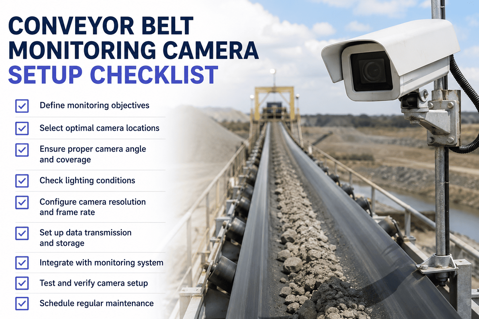
A conveyor line does not fail because the camera was missing — it fails because the camera was there, but pointed at the wrong section of belt, mounted at an angle that could not see the edge, in lighting that washed out every anomaly the model was trained to catch. Most AI monitoring deployments that under-perform in year one under-perform for reasons that were locked in during the first week of installation, when someone made a decision about mount height or field of view that nobody wrote down and nobody revisited. This checklist walks through every phase of a conveyor belt AI monitoring rollout — from the pre-install site survey through camera angles, thermal placement, lighting, network setup, alert thresholds, and the exact validation steps before the system goes live on production. If you want a working session on any phase before you install, you can book a deployment review call with our conveyor vision team.
Conveyor Monitoring · AI Deployment Checklist
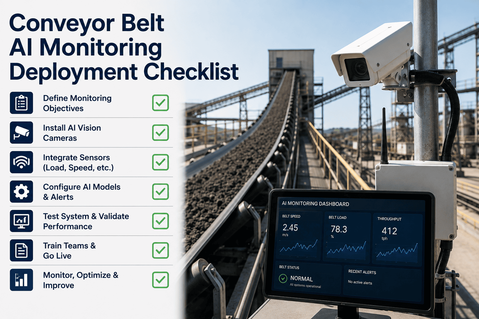
Conveyor Belt AI Monitoring Deployment Checklist
Every step of a defensible conveyor vision rollout — camera angles for belt surface and edge, thermal placement for drives and idlers, lighting for underground and covered belts, alert thresholds, and the go-live validation that keeps false alarms out of your control room.
How This Deployment Checklist Is Organized
A conveyor AI monitoring project fails or succeeds long before anyone opens the first alert. The decisions that decide whether the system catches a torn belt at 2 a.m. or floods your screens with false positives are made during the site survey, during the mounting decision, during the first week of threshold tuning. This checklist mirrors the real rollout lifecycle in seven phases so the team doing the install and the team who will operate the system afterward are working from the same document. Work through the phases in order the first time you deploy on a new line, then keep each individual checklist as a reference for the next belt, the next transfer point, the next thermal camera you add.
1Pre-Deployment Site Survey
2Surface & Edge Camera Angles
3Thermal Camera Placement
4Lighting Setup
5Network & Edge Compute
6Alert Threshold Configuration
7Go-Live Validation
Phase 1: Pre-Deployment Site Survey Checklist
Every mistake that shows up six months into a deployment — a blind spot at the tail pulley, a thermal camera looking at the wrong side of a gearbox, a lighting fixture that vibrates itself out of alignment every third shift — was almost always a survey item that got skipped, deferred, or answered from a drawing instead of a site walkdown. The survey is not a formality. It is the single phase where a two-hour investment saves a two-week reinstall. Every item below should be answered by physically standing at the location, not by looking at a P&ID from the maintenance office.
Full conveyor path walked end to end with belt running, not stopped for photos only
Belt width, speed, load type, and load variability documented per segment
Every transfer point, load zone, and discharge chute physically inspected and photographed
Historical failure log pulled — where has this line torn, mistracked, or spilled before
Ambient conditions logged — dust concentration, moisture, temperature range across shifts
Available mounting structures identified — gantries, stringers, walkway rails, catenaries
Existing lighting mapped by fixture type, height, and shadow pattern on the belt
Power availability confirmed at each candidate camera location — voltage, distance, panel
Network path documented — fiber run, wireless line of sight, or edge-only operation
Vibration levels at each mount candidate measured or estimated from adjacent equipment
Access safety confirmed for future cleaning, lens replacement, and calibration checks
Not sure what to look for during a survey walkdown? Talk to our deployment team about running one with you before your first install.
Phase 2: Surface and Edge Camera Angle Checklist
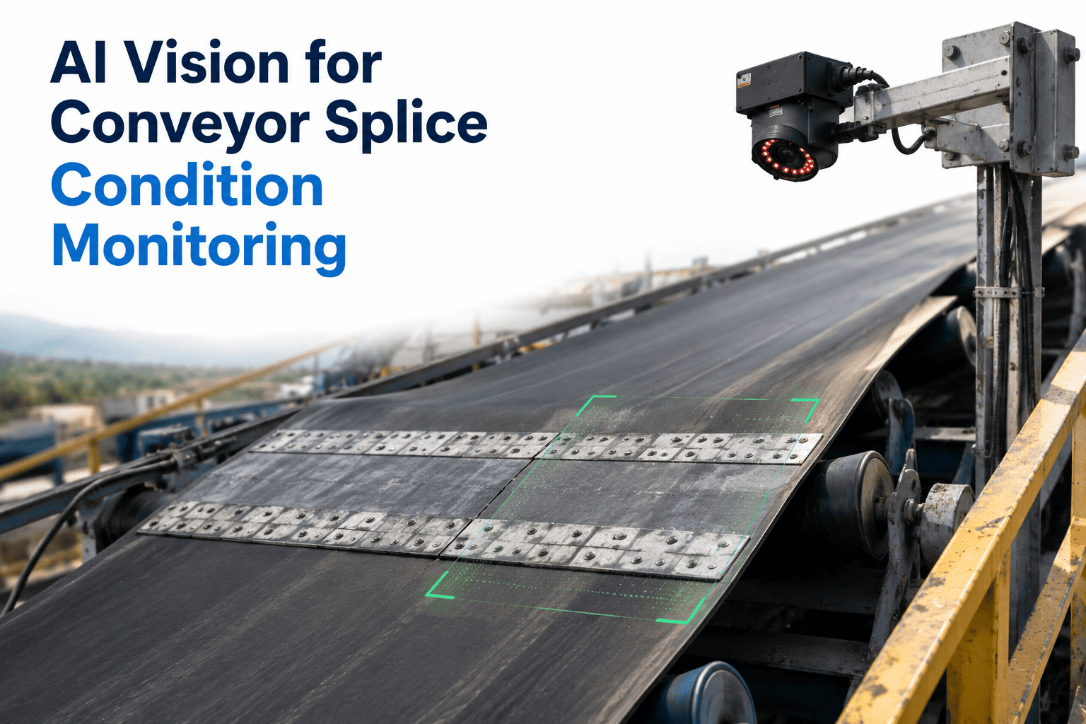
The single most common camera mistake on a conveyor deployment is mounting one camera directly overhead and calling it belt coverage. An overhead camera can see the belt surface fine — it cannot see the belt edge, cannot see mistracking against the frame, and cannot detect a fray developing on the outside three inches of the belt where most cuts start. Belt surface, belt edge, and belt profile are three separate detection tasks and they need three separate camera angles that together give the model everything it was trained to look for.
Belt Surface Camera Angles
Overhead surface camera mounted perpendicular to the belt travel direction
Field of view covers full belt width plus 100 mm margin on each side for tracking drift
Mount height calibrated so belt fills at least 70 percent of the vertical frame
Camera positioned upstream of transfer points, not directly over impact zone spillage
Shutter speed set to freeze belt motion at operating speed with zero blur
Resolution confirmed sufficient to resolve smallest target defect at the belt surface
Belt Edge and Mistracking Camera Angles
Dedicated edge camera mounted at low-angle profile view, not overhead
Frame captures both belt edge and adjacent structure or stringer as reference line
Second edge camera on opposite side for symmetric mistracking detection on wide belts
Edge cameras positioned near tail and head pulleys where mistracking is most visible
Frame margin allows drift measurement without belt leaving field of view entirely
Return Side and Underside
Return-side camera positioned to capture carryback buildup on the belt underside
View angled to see full width of underside, not just centreline
Return idler zones covered where cover damage and edge fray first become visible
Mount protected from falling material and dust accumulation on the lens
Detection Coverage Zones at a Glance
| Zone | Camera Type | Angle | What It Catches |
|---|
| Head pulley discharge | Optical, overhead | Top-down over discharge | Flow disruption, oversized material, plugging |
| Load zone | Optical, overhead | Perpendicular to belt | Overload, off-centre loading, spillage at skirts |
| Belt centre span | Optical, overhead + edge | Top-down + low-angle profile | Surface cuts, longitudinal rips, fray, mistracking |
| Return side | Optical, underside view | Upward-facing profile | Carryback, cover damage, edge wear |
| Drive pulley & gearbox | Thermal | Direct line of sight | Bearing heat rise, gearbox oil temperature drift |
| Idler frames | Thermal panning or fixed arrays | Roller housing line of sight | Seized bearings, blocked idlers, friction hot spots |
Phase 3: Thermal Camera Placement Checklist
Thermal on a conveyor is not a spot check anymore. A seized idler bearing produces a temperature signature days before the belt starts to smell hot, and a drive motor bearing drifts up degrees at a time across shifts long before it triggers a vibration alarm. The placement mistake most sites make is treating thermal as a walk-by tool bolted to a fixed mount — thermal cameras placed for continuous monitoring need direct line of sight to the exact bearing housing or motor surface you want to track, not a general area shot of the drive skid.
Drive motor thermal camera aimed directly at bearing housing, not motor casing
Gearbox thermal camera positioned to read oil sump housing surface temperature
Head, tail, and take-up pulley bearings each within a dedicated thermal field of view
Idler thermal camera arrays cover carry-side idlers at highest-load section of belt
Return-side idlers included in coverage — often the first to seize under carryback
Baseline temperature captured for every bearing during normal operation before go-live
Ambient temperature reference channel configured for compensation across shifts
Line of sight verified with no steam, dust plume, or belt structure blocking the sensor
Mount distance within the sensor's calibrated measurement range for accuracy
Housing rated for the ambient conditions — heat, dust ingress, wash-down where applicable
Bulk material temperature monitored separately where combustible material is carried
Deploying Thermal on a Live Conveyor for the First Time?
Every thermal placement mistake compounds — a camera pointed at the wrong bearing housing gives you a working system that misses the exact failure mode you bought it to catch. A short review with our team before you drill mounting holes is the cheapest insurance in the whole project.
Phase 4: Lighting Setup Checklist
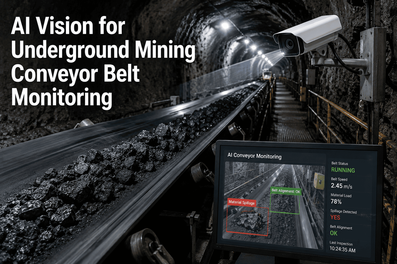
A vision model trained on well-lit belt footage does not fail on a poorly-lit belt — it produces false positives that erode trust in the system within two weeks of go-live. Underground conveyors, covered galleries, tunnel belts, and long overland runs at night share the same problem: whatever ambient lighting exists was designed for humans to walk past, not for a camera to inspect at high shutter speed. Correct lighting for AI monitoring means dedicated fixtures, positioned to eliminate shadows across the full belt width, matched to the shutter and gain the camera will actually run in production.
Belt illuminance measured at the point of capture, not at the walkway rail
Dedicated LED fixtures added anywhere ambient lighting falls below the camera minimum
Light source angled to avoid direct reflection off the belt surface into the lens
Shadow pattern across belt width verified — no dark bands from structure or stringers
Colour temperature consistent across all fixtures on the same camera view
Underground and enclosed belt fixtures rated for the dust and gas classification of the area
Backlighting or dark-field illumination used where contrast on dark bulk material is low
Structured light considered for surface defect detection at high belt speeds
Outdoor belts tested at dawn, midday, dusk, and night to confirm camera performance range
Lens cleaning access confirmed for the same locations that carry the lighting fixtures
Phase 5: Network and Edge Compute Checklist
A conveyor vision system that depends on a stable connection back to a central server is a system that goes blind every time the plant network hiccups. Edge inference is not a nice-to-have on industrial conveyors — it is the design principle that keeps the alerts flowing when the fiber gets cut by a forklift or the wireless link fades in a dust storm. This checklist covers the network and compute topology that decides whether your monitoring survives the first bad day.
Edge processor sized for the camera count and model complexity at each location
Inference confirmed to continue during full loss of central network connectivity
Local alert output wired directly to PLC or safety system where line stop is required
Enclosures rated to IP65 or higher where dust and moisture exposure is expected
Cabling path protected from mechanical damage, belt spillage, and rodent activity
UPS or protected power supply on every edge node to survive brief power events
Data retention window defined for video buffer — how far back can you scrub after an event
Integration path confirmed with existing SCADA, CMMS, and maintenance dashboards
Bandwidth allocation confirmed for video streaming during incident review, not just alerts
Cybersecurity review completed — network segmentation, authentication, patch strategy
Trying to fit AI monitoring into an existing OT network without breaking segmentation rules? Our integration team has done it on plants with strict IEC 62443 environments.
Phase 6: Alert Threshold Configuration Checklist
A monitoring system with the wrong alert thresholds does not silently under-perform. It actively trains your control room to ignore it. Two false positives per shift for one week and every operator on the floor has already learned to swipe the notification off the screen without looking. Threshold configuration is where the deployment either becomes a trusted tool or becomes shelf-ware, and the difference is almost always whether the thresholds were tuned per location on real production footage instead of copied from a spec sheet.
Baseline and Sensitivity
Baseline footage collected across every shift, load pattern, and material variation
Baseline explicitly includes wet, dusty, and low-light periods, not clean daytime only
Detection sensitivity tuned per camera location, not one setting across the whole line
Known false-positive triggers logged and either suppressed or scheduled around
Severity and Routing
Alert severity levels defined — informational, action-required, immediate line stop
Escalation path documented per severity — who is notified, in what order, on what channel
Line-stop alerts wired to PLC only where downstream damage justifies automatic stop
Every alert routes into the CMMS as a work order with image and location attached
Thermal-Specific Thresholds
Absolute temperature thresholds set with reference to bearing manufacturer limits
Delta thresholds set against ambient and against symmetric bearings on the same shaft
Trend-based thresholds enabled — sustained rise over shifts triggers alert before absolute limit
Hot material carriage thresholds separated from equipment thermal thresholds
Phase 7: Go-Live Validation Checklist
Go-live is not the day the cameras come online. Go-live is the day operations agrees to trust the alerts, which is a completely different milestone. Between the two there is a validation period where the system is generating alerts and the maintenance team is confirming that the alerts match what they see when they walk the belt. Skipping this phase is what produces the deployment that technically works but nobody uses.
Every camera view reviewed frame-by-frame against expected field of view diagram
Detection confirmed on staged test defects at every camera location, not just one
Thermal baseline verified against handheld thermal readings at every bearing
Alert routing tested end to end — camera to edge to CMMS work order to assigned owner
False positive rate measured over first full production week and tuned before handover
Operator training completed — how to review, acknowledge, and escalate an alert
Maintenance training completed — how to interpret alert history and trend data
Ownership documented — who tunes thresholds going forward, who owns lens cleaning
Handover sign-off completed only after a full week with zero unresolved false positives
Deployment Coverage Outcomes
Full-Width
Surface and edge coverage on every high-risk belt segment
Continuous
Thermal watch on every drive, gearbox, and critical bearing
Trusted
Alerts routed straight into CMMS with owner and evidence attached
What Not to Do During Deployment
Every long-running conveyor monitoring program collects the same short list of installation mistakes — patterns that seemed sensible during install and became painful three months in. Reviewing them once before you drill your first mount is cheaper than living with any one of them for a year.
Mounting a single overhead camera and calling it belt coverage when edge is the failure mode
Copying threshold values from a spec sheet instead of tuning against local baseline footage
Placing thermal cameras where a steam plume or dust cloud crosses the line of sight
Relying on plant ambient lighting without measuring illuminance at the actual belt surface
Deploying without an edge processor so a network drop takes the whole system offline
Sending every detection as the same severity — operators tune it all out within a week
Handing over the system before a full production week with an acceptable false positive rate
Frequently Asked Questions
How many cameras does a typical conveyor deployment need to get started?
Camera density is driven by the number of transfer points, load zones, and mistracking-prone segments on the belt, not by raw belt length. A mid-size industrial conveyor network usually starts with eight to fifteen cameras covering the highest-value monitoring points — head and tail pulleys, load zones, and critical transfer chutes — and then expands from there based on the events the first phase catches. Long overland belts often start with three to five cameras positioned at the highest-consequence locations and grow with recovered value. Our team can help you scope this against your specific belt layout during a
deployment planning call.
Can this system integrate with our existing PLC, SCADA, and CMMS without ripping anything out?
Yes. AI vision on conveyors is designed as an overlay, not a replacement, and it connects to existing PLC, SCADA, and CMMS platforms through standard industrial protocols so alerts, images, and trend data land in the dashboards your operators and maintenance teams already use every day. No existing conveyor hardware needs to be modified for the vision layer to come online, and the alert routing is typically live within the first week of installation.
Our integration team can walk through the specific protocols against your control system if you want to confirm the fit before you commit.
How long does a full deployment from survey to production go-live actually take?
A typical single-line deployment runs six to twelve weeks from site survey to trusted production alerts, with roughly two weeks of survey and design, three to six weeks of installation and initial commissioning, and one to two weeks of threshold tuning and validation before formal handover. Larger multi-line rollouts stagger installation phase by phase so operations sees value on the first line while later lines are still in survey. Timeline compression is usually possible when the plant has recent electrical drawings and clear network paths already documented.
What is the biggest single deployment mistake that produces false alarms?
The most common single cause of false alarms in the first month is a mismatch between baseline footage and real operating conditions — a system tuned only on clean daytime footage will fire constantly on the first wet night shift because the model is reacting to lighting change instead of a real defect. Collecting baseline across every shift, load pattern, and weather condition before finalizing sensitivity is the fix, and it is the single item most likely to be skipped when a project is running behind schedule. If the alerts started firing after go-live and never really settled down, that is almost always the diagnosis.
Does the system keep working if we lose network connectivity to the central platform?
Yes, provided the deployment is designed around edge inference from the start rather than depending on a round trip to a central server for every frame. Edge processors installed at each camera cluster continue running detection models even during full loss of central connectivity, storing events locally and routing critical alerts to the PLC or local operator station until the network path recovers. This is a design decision worth confirming during Phase 5 rather than discovering during the first network outage —
talk to our team if you want to walk through the edge architecture in detail.
Turn This Checklist Into a Working Deployment on Your Lines
Our conveyor vision team can walk this entire checklist against your specific lines, layout, and operating environment — starting with a free deployment review that maps camera positions, thermal placement, and alert thresholds against your actual belt network before any hardware ships. Six to twelve weeks from survey to trusted alerts routed into your CMMS.