Conveyor Belt Monitoring Camera Setup Checklist

By Johnson on July 22, 2026

conveyor-belt-monitoring-camera-setup-checklist

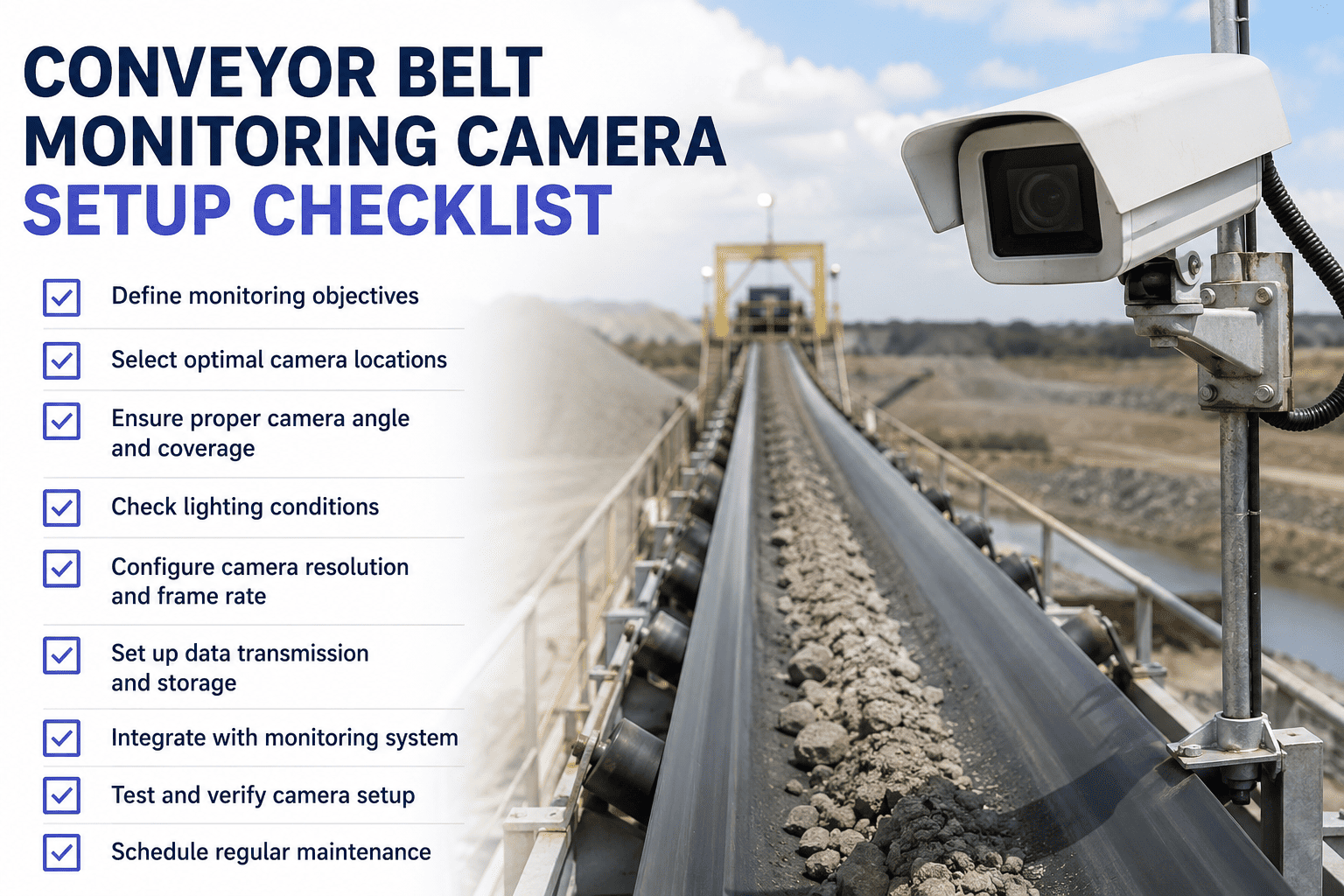
Conveyor belt misalignment is silent and progressive — by the time an operator notices the belt has been riding the edge for two hours, the frame damage and belt fraying are already done. AI vision cameras can catch tracking deviations as small as 15 millimeters, well before edge contact occurs, but only if the camera is actually positioned to see the belt edge, the splice, and the surface under consistent lighting. A camera aimed wrong or lit poorly will either miss real defects or flood the alert queue with false trips from shadows and dust. This checklist covers the five setup zones that determine whether your conveyor camera actually catches what it is meant to catch. Book a demo to see conveyor camera setup built into iFactory's deployment process.

Five Coverage Zones Along Every Monitored Conveyor
1Surface
2Edge Tracking
3Splice
4Lighting
5Alert Thresholds

Each zone below maps to a specific failure mode this checklist prevents — from edge tearing to a splice separating mid-run. Skipping a zone leaves that failure mode invisible to the camera.

15mm
Smallest belt edge tracking deviation a correctly positioned camera can reliably detect
2-8 wks
Typical advance warning window AI vision provides before splice or wear-related failure
95%+
Detection accuracy achievable even in dusty, low-light conveyor environments with proper setup
<200ms
Detection latency from image capture to alert generation on correctly configured edge hardware

Zone 1: Belt Surface Camera Angle and Coverage

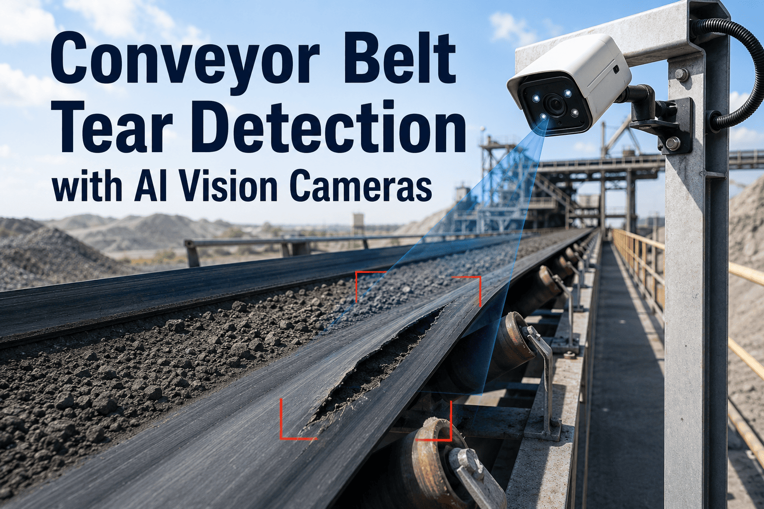
Surface cameras catch longitudinal rips, cord exposure, cover wear, and foreign material before they progress into a belt tear. Coverage gaps between camera stations are where these defects go unnoticed until they have already grown large enough to threaten the belt structurally.

Camera mounted perpendicular to belt travel direction with full belt width visible in a single frameCritical
Mounting height and angle confirmed to capture belt surface texture clearly enough to distinguish wear from shadowCritical
Camera spacing along the conveyor route calculated to eliminate blind spots between adjacent coverage zonesCritical
Return-side camera included where underside material accumulation or roller contact damage needs monitoringMonitor
Frame rate matched to belt speed so surface defects are captured clearly rather than blurred by motionMonitor

Zone 2: Edge Tracking and Alignment Coverage

Belt mistracking is one of the most common causes of unscheduled conveyor downtime, and it is entirely preventable if the camera can see the edge position relative to the idler frame continuously. Start free trial to see edge tracking configuration tested against your own belt footage.

Camera positioned to track belt edge position against the idler frame centerline at sub-centimeter resolutionCritical
Reference centerline calibrated against the physically confirmed correct tracking position, not an assumed defaultCritical
Lateral deviation tolerance set per conveyor based on belt width, speed, and structural clearance to the frameMonitor
Camera coverage confirmed at transfer points and curves where mistracking risk is highest along the routeMonitor
Normal belt wander during loading variation distinguished from problematic drift in the detection model configurationRoutine

Zone 3: Splice Area Coverage and Recognition

Splice joints are the single most common failure point on any conveyor belt, and they fail progressively — surface separation, fastener protrusion, or belt lift at the joint all develop over weeks before a full separation event. A camera that cannot recognize and track the same splice pass after pass cannot build the trend data that catches this early.

Splice recognition confirmed to identify and track the same joint consistently across every belt revolutionCritical
Camera shutter speed and positioning tested to capture a clear, non-blurred image of the splice at full belt speedCritical
Splice gap width baseline recorded at setup to enable trend tracking of gap growth over subsequent weeksMonitor
Multiple splices on the same belt each assigned a unique tracked ID rather than aggregated into one readingMonitor
Fastener protrusion and belt lift at the joint included as distinct detection categories, not folded into general wearRoutine
Setup Tip

Splice tracking depends on consistent recognition, not just image quality. If the model re-identifies the same splice as a new joint on every pass, gap-width trending is impossible and the system will never build the weeks-long trend that gives early warning before separation.

Zone 4: Lighting Configuration for Belt Color and Material

Lighting is where most conveyor camera setups quietly fail without anyone realizing it. Dark rubber belts, dusty environments, and inconsistent ambient light between day and night shifts all degrade image quality in ways that either hide real defects or generate a flood of false alerts from shadows.

Lighting intensity calibrated for the specific belt color and material — dark rubber requires different exposure than lighter fabric beltsCritical
Consistent artificial lighting installed so detection accuracy does not vary between day shift and night shift conditionsCritical
Dust and particulate interference tested under actual operating conditions, not a freshly cleaned commissioning environmentMonitor
Glare from wet or reflective belt surfaces checked and corrected through lighting angle adjustment rather than software aloneMonitor
Lighting fixtures rated for the ambient temperature, vibration, and any hazardous area classification of the installation zoneRoutine

Zone 5: Alert Threshold Configuration

A camera set up perfectly still fails the plant if the alert thresholds are wrong — too sensitive and the team drowns in false trips within a week, too loose and a developing tear runs unnoticed until it becomes an emergency shutdown. Book a demo to see threshold tuning against your own conveyor data before go-live.

Edge deviation alert threshold set based on belt width and structural clearance, not a generic default valueCritical
Splice gap growth rate threshold configured so replacement scheduling happens weeks before the failure risk zoneCritical
Severity tiers defined so minor surface wear queues for scheduled review while active tears trigger immediate alertsMonitor
Alert volume simulated against a full shift of real footage before enforcement mode activates on the live lineMonitor
Belt thickness wear threshold set to trigger planned replacement work orders before reaching the failure risk zoneRoutine

Setup Zone Summary: Time, Ownership, and Scope

Zone Setup Duration Owner Critical Items Total Items
1. Belt Surface Coverage 1 to 2 days Field Technician 3 5
2. Edge Tracking 1 day Reliability Engineer 2 5
3. Splice Coverage 4 to 6 hours Reliability Engineer 2 5
4. Lighting Configuration 1 day Field Technician 2 5
5. Alert Thresholds 2 to 3 days Maintenance Manager 2 5

Let iFactory Configure Every Zone for Your Conveyor Network

iFactory's team maps camera coverage, calibrates lighting for your specific belt material, sets splice tracking per joint, and tunes alert thresholds against real footage from your line — before a single alert reaches your team.

What Correctly Configured Conveyor Monitoring Prevents

15mm
Earliest Tracking Deviation Caught
Before edge contact with the frame occurs, when caught at this stage instead of after visible damage
2-8 wks
Advance Warning Window
Ahead of splice separation or wear-related belt failure when trend tracking is properly configured
95%+
Detection Accuracy
Achievable even in dusty, harsh conveyor environments once lighting and angle setup is correct
Weeks
Not Emergency Shutdowns
Time to plan belt replacement or splice repair instead of reacting to a catastrophic tear

Frequently Asked Questions

QHow many cameras does a typical conveyor line need for full coverage?
Camera count depends on conveyor length, belt speed, and how many distinct failure modes need monitoring — a short transfer conveyor may need a single well-positioned camera covering surface and edge tracking together, while a long overland conveyor with multiple splices typically needs dedicated cameras spaced to eliminate blind spots between coverage zones. Transfer points and curves generally warrant additional coverage since mistracking risk concentrates at these locations. Book a demo to get a camera placement plan specific to your conveyor route.
QDoes conveyor monitoring require replacing existing camera infrastructure?
No, in most cases industrial cameras already installed above conveyor lines can connect to an edge AI processing unit without replacement, provided they meet the angle, resolution, and lighting requirements covered in this checklist. The more common adjustment is repositioning or adding supplemental lighting rather than swapping out the physical cameras, since most existing installations were mounted for general visibility rather than the specific framing AI detection models need for edge tracking and splice recognition.
QHow does the system tell the difference between normal belt wander and a real mistracking problem?
The detection model is configured with tolerances for displacement, angle, and duration, distinguishing brief normal wander during loading variation from sustained drift that indicates a genuine tracking issue. This distinction is set during Zone 2 and Zone 5 configuration in this checklist, using the belt's actual operating behavior as the baseline rather than an assumption of what normal should look like. Getting this threshold right is what prevents the system from generating alerts every time the belt shifts slightly under normal load changes.
QCan this checklist be applied to conveyors carrying different materials, like cement clinker versus food product?
Yes, the five setup zones apply across material types, though the specific lighting calibration in Zone 4 and detection thresholds in Zone 5 need adjustment per material and belt color. A dark rubber belt carrying clinker in a cement plant needs different exposure settings than a lighter fabric belt in food processing, and dust or particulate interference varies significantly between environments. Start free trial to configure setup parameters specific to your material handling application.
QWhat happens to splice tracking data when a belt is repaired or re-spliced?
When a splice is repaired or a belt is re-spliced, the tracked joint ID should be reset with a new baseline gap width recorded at the time of repair, rather than carrying forward the old trend data that no longer reflects current condition. Continuing to compare against pre-repair measurements would either mask genuine new degradation or generate false alerts based on outdated baseline data. Confirming this reset happens correctly after any splice work is a good practice to build into your standard maintenance closeout procedure.

Set Up Every Conveyor Camera Right the First Time

iFactory's AI vision platform covers belt surface, edge tracking, splice recognition, and lighting calibration for every conveyor in your plant, turning confirmed anomalies into work orders with the camera frame attached as evidence.


Share This Story, Choose Your Platform!