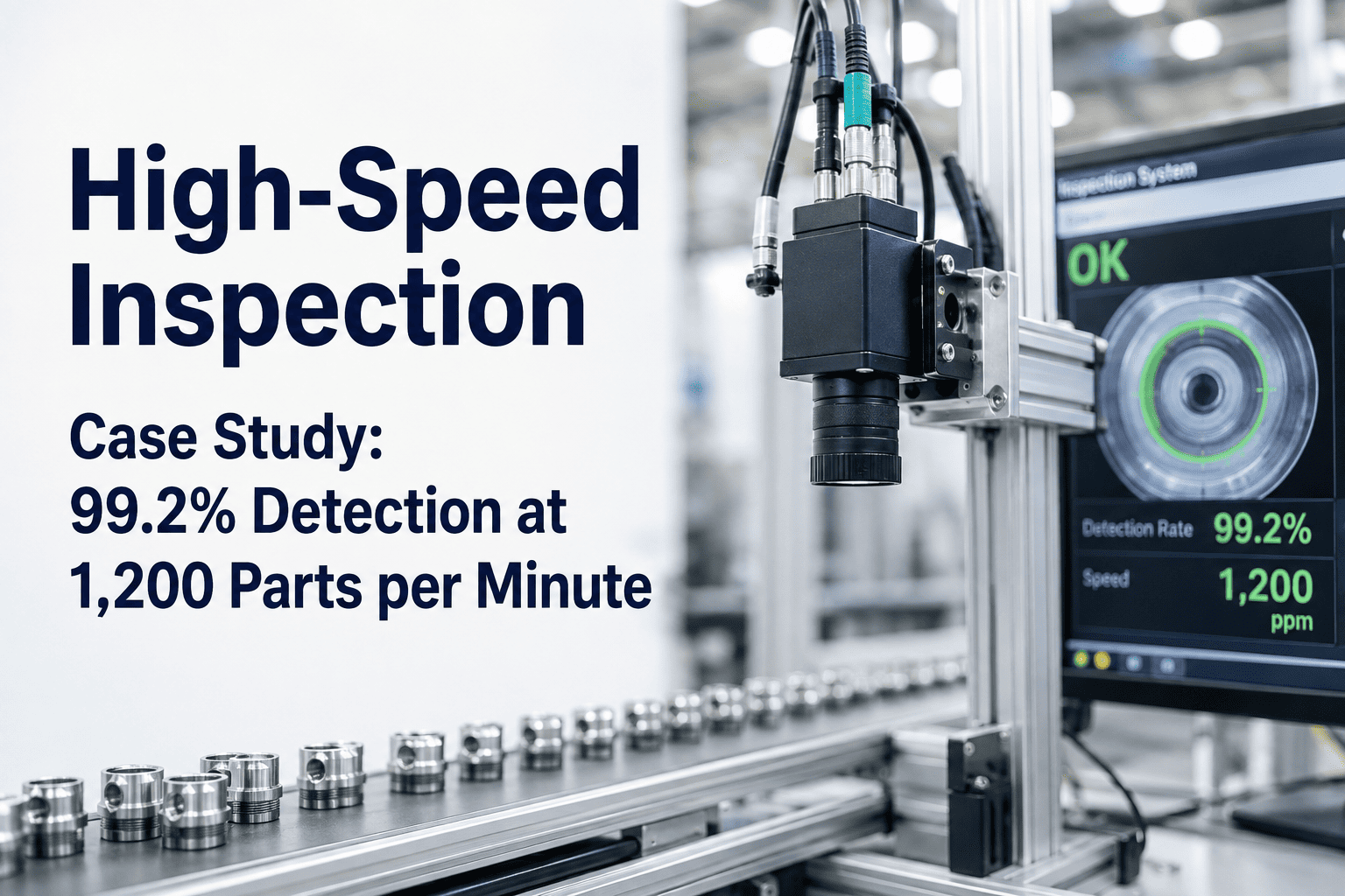
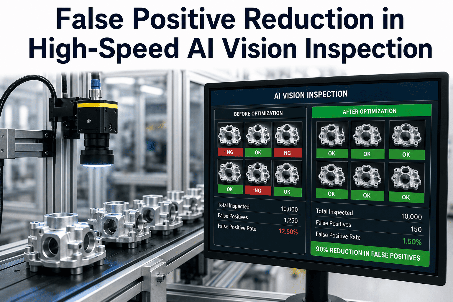
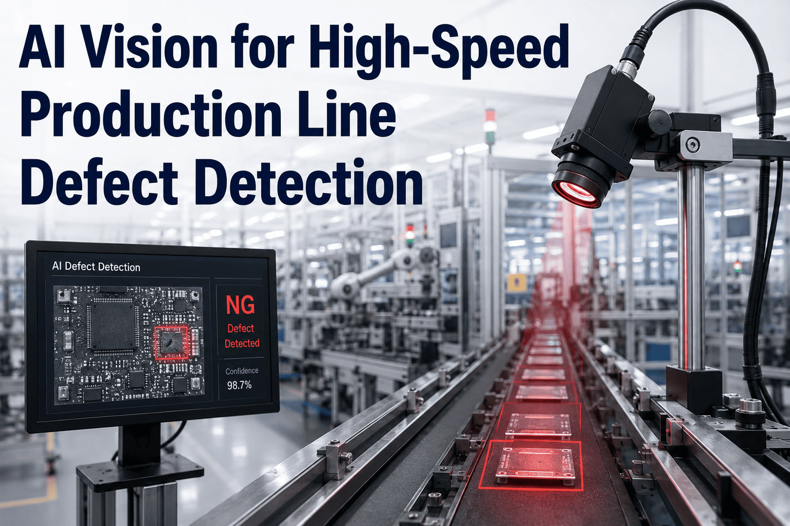
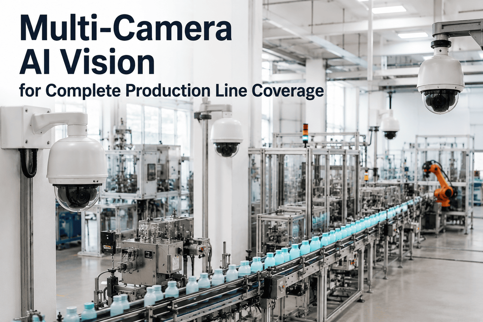
A vision system that works perfectly at 30 parts a minute can fall apart completely at 300. The camera that caught every defect in testing starts missing them at full speed, the reject arm fires a beat late and kicks the wrong part, and the strobe that looked bright enough in the lab turns every frame into a smear. High-speed deployment isn't a slow pilot scaled up — frame rate, trigger timing, and reject latency all need recalculating against your real line speed first. See how iFactory's AI Vision Camera platform handles this end to end.
Production QC · High-Speed Vision · Deployment Checklist
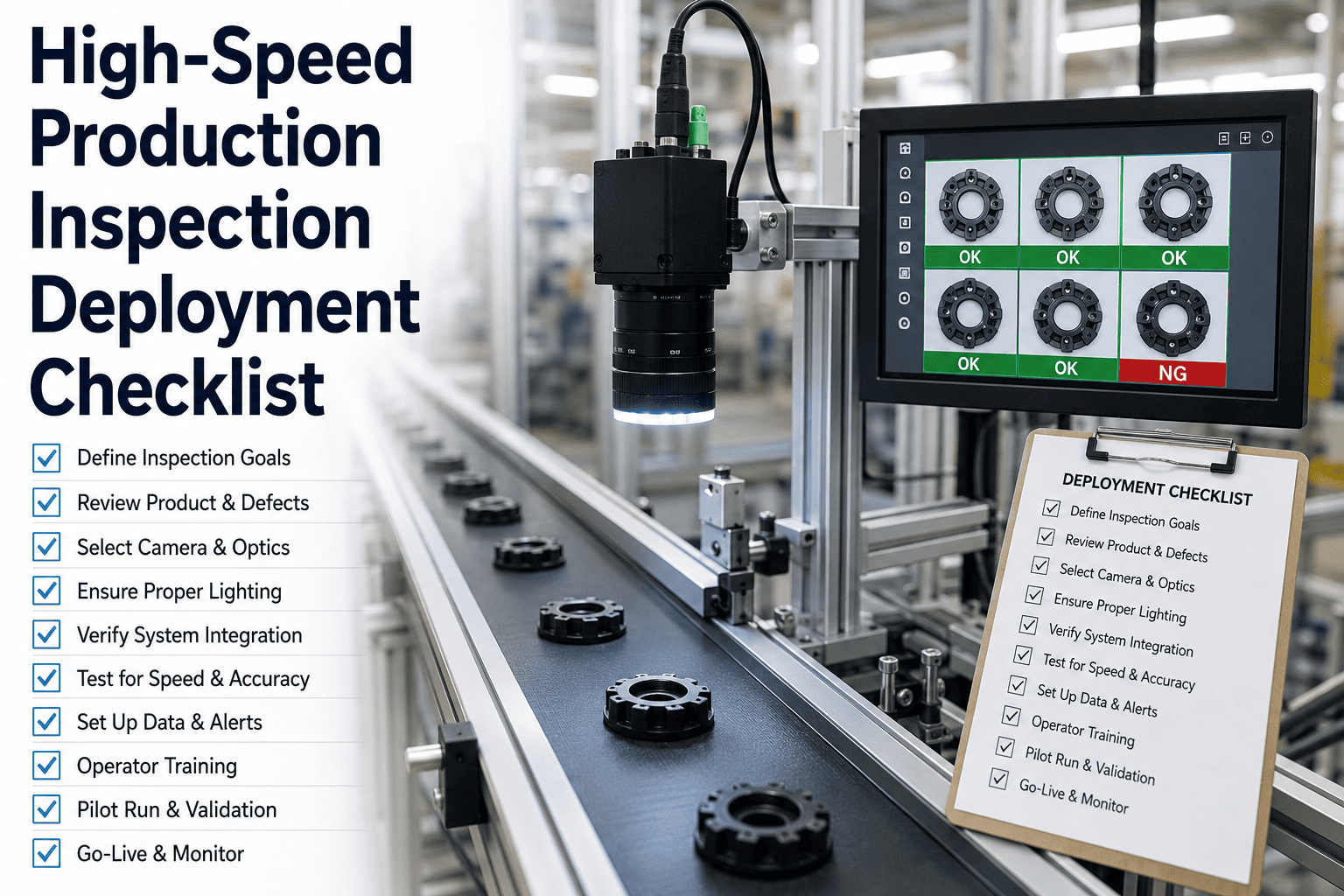
High-Speed Production Inspection Deployment Checklist
Six components a high-speed inline vision deployment actually needs — frame rate math, trigger mechanism, strobe sync, model training, reject integration, and accuracy validation — built for lines that don't slow down for the camera.
100µs
Minimum exposure time needed to resolve a 1mm feature at 10m/sec line speed without blur
200-500ms
Typical air-cylinder reject actuator reaction time — the real bottleneck in most reject chains
Encoder-Based
The trigger method needed once line speed varies rather than running perfectly uniform
Why Speed Changes Everything
A Low-Speed Pilot Doesn't Predict High-Speed Performance
A camera and lighting rig validated on a slow test line proves the model can detect the defect — it proves nothing about whether the system can detect it in motion, trigger at the right instant, and get a reject signal to the right actuator before the part travels past it. Every component below behaves differently once line speed climbs: exposure time that was generous at low speed becomes a blur risk, a timed-delay trigger that worked on a steady conveyor drifts the moment speed varies, and a reject mechanism with plenty of margin at low throughput suddenly has to hit a window measured in milliseconds.
Section 01 — Frame Rate vs. Line Speed Calculation
Sizing the Camera to the Line, Not the Other Way Around
Frame rate and exposure time are not independent settings to tune after installation — they are calculated directly from line speed, part size, and the smallest defect the system needs to catch. Getting this calculation wrong is the single most common reason a working demo becomes an unreliable production system.
Worked example
A 1mm defect needs to stay sharp at a line speed of 1 meter per second. The shutter-speed rule caps exposure at defect size ÷ 5 ÷ line speed — here, 1mm ÷ 5 ÷ 1000mm/sec, or 200 microseconds. Set exposure longer than that and the part smears across more than a fifth of the defect's own size during capture, and a real defect can blur into the background.
Frame Rate Sizing Checklist
Actual line speed is measured at full production rate, not the rate the line runs during testing or changeover, since frame rate sized for a slower test run will fall short in production
Input: Measured line speed at max throughput
The smallest defect the system must catch is defined explicitly, since exposure time and required resolution are both calculated backward from that single number
Input: Minimum detectable defect size
A global shutter sensor is specified rather than a rolling shutter for any part in continuous motion, since rolling shutter exposes each row at a slightly different instant and distorts fast-moving objects
Input: Shutter type confirmed for motion
Camera resolution is verified against the field of view and smallest feature together, not resolution alone, since a high-megapixel sensor with too wide a field of view still under-resolves a small defect
Input: Resolution vs. field-of-view check
Margin is built into the frame rate calculation for peak line speed and speed variability, rather than sizing exactly to the nominal average rate
Input: Peak-speed margin, not average
Section 02 — Trigger Mechanism
Firing the Camera at the Right Instant, Every Time
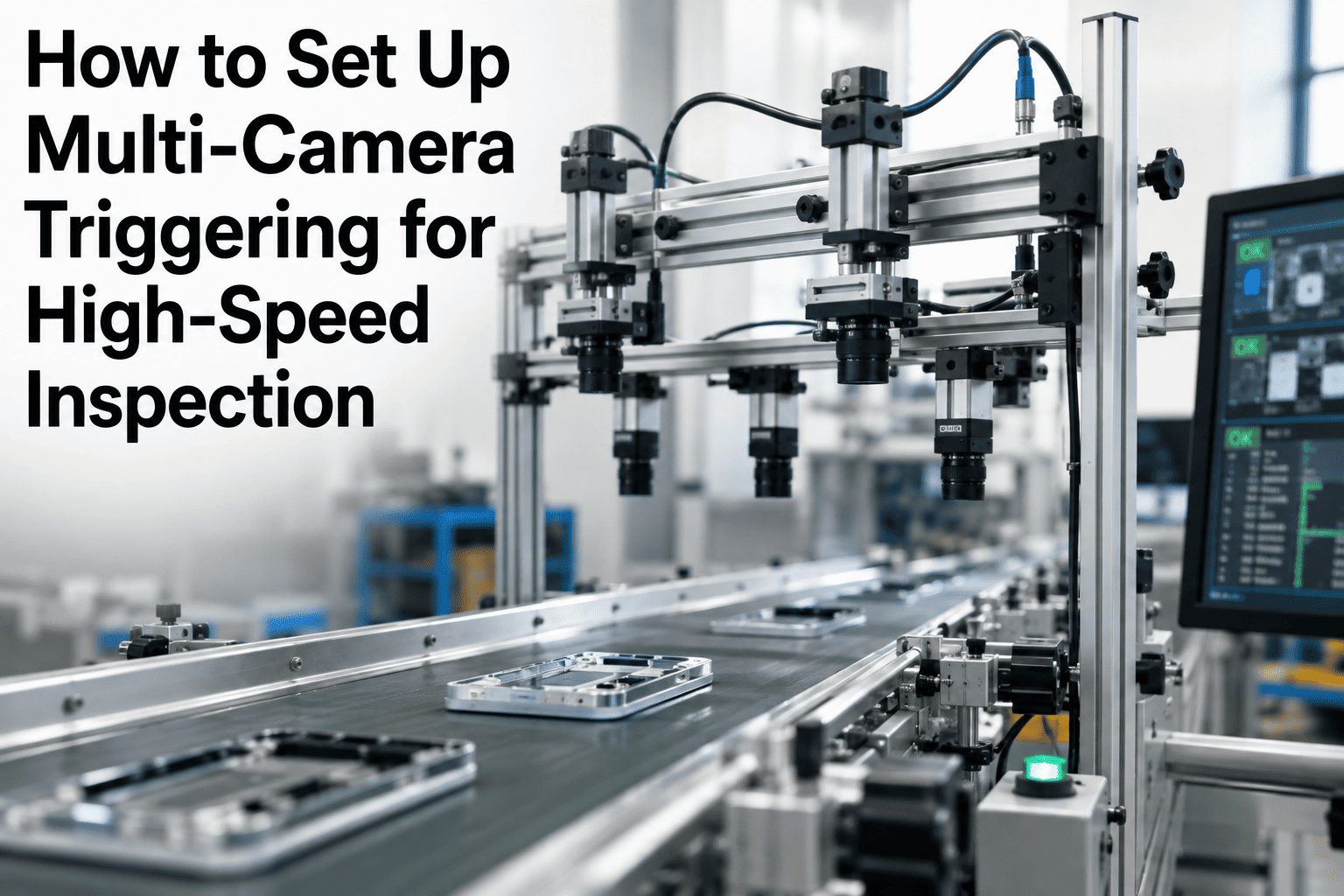
A camera needs to know exactly when a part is in position — triggering off a timed delay works only if the line runs at a perfectly constant speed, which few real lines do. The moment speed varies, a fixed-delay trigger drifts out of position, and the more reliable approach is an encoder that ties the trigger to actual belt travel distance instead of elapsed time.
Timed-Delay Trigger
Fires a fixed interval after a presence sensor detects a part. Simple to configure, but only accurate if the line runs at a genuinely constant speed between the sensor and the camera.
Drifts if speed varies
Encoder-Based Trigger
Ties the trigger to actual conveyor travel distance via encoder pulses rather than elapsed time, so the camera fires at the correct position regardless of speed changes, stops, or reversals.
Holds position through speed changes
Timing budget
Camera trigger latency itself is typically only a few microseconds, and LED strobe trigger latency is smaller still — the real timing budget gets consumed elsewhere, in image processing time, PLC response, and the reject actuator itself. Design the whole chain, not just the camera trigger, against your actual line speed.
Section 03 — Lighting Strobe Synchronization
Freezing Motion With Light Instead of Shutter Speed Alone
At high line speeds, continuous lighting alone often can't deliver enough intensity for the short exposure times the math above requires — a strobed light source fires a brief, high-intensity pulse timed to exactly overlap the camera's exposure window, effectively freezing motion that continuous lighting cannot.
Strobe Sync Checklist
Strobe pulse duration is set shorter than the camera's exposure time by a defined safety margin, so the light source is confirmed fully on for the entire exposure window
Sync rule: Exposure time set longer than strobe pulse duration
The strobe trigger signal is wired from the camera's own output line rather than a separate independent timer, so pulse timing tracks the camera's actual exposure trigger rather than an approximation of it
Sync rule: Camera-driven strobe trigger, not independent timer
Rising-edge or falling-edge trigger polarity is explicitly confirmed against the lighting controller's wiring configuration, since a polarity mismatch causes the strobe to fire outside the exposure window entirely
Sync rule: Trigger edge polarity confirmed and tested
Strobe intensity and angle are validated against the specific defect type being detected, since surface, edge, and subsurface defects each respond differently to bright-field versus dark-field lighting
Sync rule: Lighting technique matched to defect type
Deploy a vision system sized to your actual line speed from day one — frame rate, trigger, strobe sync, and reject timing calculated against your real production numbers, not a bench test.
Section 04 — Model Training for Line-Speed Conditions
Training on Images That Actually Look Like Production
A model trained exclusively on clean, well-lit, low-speed sample images learns to recognize defects under conditions the production line rarely produces. Training data needs to reflect the real image quality the camera will deliver once it is running at full line speed under the actual strobe lighting configuration — motion characteristics, part orientation variability, and lighting consistency all included.
01Capture training images at actual production line speed under the final strobe lighting setup, not bench conditions
02Include the full range of part orientation, positioning, and minor cosmetic variation the line naturally produces
03Deliberately include known-good parts with visual characteristics close to a real defect, to sharpen the pass/fail boundary
04Validate accuracy separately at low, average, and peak line speed rather than a single blended accuracy number
Section 05 — Reject Mechanism Integration
Getting the Reject Signal to the Right Part in Time
Detecting a defect correctly is only half the job — the reject signal then has to travel through image processing, a PLC, and an actuator, and physically remove the correct part before it travels past the reject gate. On a fast line, the actuator itself is often the actual bottleneck: an air-cylinder reject mechanism commonly needs on the order of 200 to 500 milliseconds to react, which can be far slower than the camera and processing stage combined.
| Chain Component |
Typical Latency Range |
Deployment Implication |
| Camera trigger |
Microseconds |
Rarely the bottleneck once properly synced |
| Image processing / inference |
1 to 300+ milliseconds |
Scales with model complexity and hardware |
| PLC response |
Fractions of a millisecond to a few ms |
Fast relative to the mechanical stage |
| Air-cylinder reject actuator |
200 to 500 milliseconds |
Usually the real constraint on reject window |
Reject Sync Checklist
Part tracking from camera to reject gate is synchronized to encoder position, so a defect identified at the camera stays correctly associated with the physical part even with several parts in between
Verify: Encoder-based part tracking, not elapsed time
Total chain latency — capture, processing, PLC, and actuator combined — is measured against the physical travel time between the camera and the reject gate at peak line speed
Verify: End-to-end latency budget tested at peak speed
The reject gate's physical distance from the camera is set with enough margin to absorb the slowest component in the chain, typically the actuator itself
Verify: Camera-to-gate distance sized to slowest link
Section 06 — Accuracy Validation at Production Speed
Proving the System Works at Full Speed, Not Just at Bench Speed
A validation run at reduced line speed proves less than it appears to — motion blur, strobe timing margin, and reject-chain latency all behave differently at full throughput. Accuracy needs to be measured with the line running at its actual production rate, including planned speed excursions, before the system is trusted to run without a human safety net behind it.
Peak, Not Average
Validation should run at maximum line speed, not the typical or average rate the line usually holds
Known Defects
A seeded set of known-defective parts run through the live line confirms detection rate under real conditions
Confirmed Reject
Each detected defect is confirmed physically ejected at the gate, not just flagged in software
What Goes Wrong
Common Deployment Pitfalls
Frame rate sized to average, not peak
The system is calculated against the line's typical speed instead of its maximum, so it works fine most of the day and fails exactly when throughput ramps up.
Fixed-delay trigger on a variable-speed line
A timed-delay trigger that looked fine in testing drifts out of position the moment the line speeds up, slows down, or briefly stops.
Strobe polarity mismatch
The strobe fires outside the camera's exposure window due to a rising/falling edge mismatch, producing dark or inconsistently lit frames that look like a camera fault.
Training data captured at bench speed
The model learns to recognize defects in clean, low-speed sample images that don't resemble what the camera actually delivers once the line is running at full speed.
Reject actuator ignored in the timing budget
Camera and processing latency get carefully calculated while the actuator's own 200-500ms reaction time is left out of the budget entirely.
Validation run at reduced speed
The system passes every test at a slower validation speed and is declared production-ready without ever being proven at actual peak throughput.
FAQs
Frequently Asked Questions
How do I know if my line is actually "high speed" for vision inspection purposes?
There isn't a single universal cutoff, since the right answer depends on part size and the smallest defect you need to catch rather than raw line speed alone — a slow-moving large part and a fast-moving small part can demand very similar exposure and frame-rate math. A practical way to check is to run the exposure-time formula in the frame rate section against your actual line speed and minimum defect size: if the required exposure comes out under roughly a millisecond, you're in territory where standard continuous lighting and a fixed-delay trigger are likely to fall short, and the components in this checklist become relevant rather than optional.
Book a demo and bring your line speed and defect size — it takes minutes to run the numbers together.
Do I need a line-scan camera instead of a standard area-scan camera at high speed?
Not necessarily — the general rule of thumb used across the industry is that objects moving above roughly 40 km/h are better suited to line-scan cameras, which capture one line of pixels at a time and build the full image from continuous motion, while most production-line speeds are comfortably handled by area-scan cameras with a properly calculated frame rate and global shutter. Area-scan is simpler to integrate and sufficient for the overwhelming majority of packaging, assembly, and inline QC applications; line-scan becomes the better fit for continuous webs and very high-speed continuous processes like sheet or film production.
What's the most common cause of a high-speed vision system missing defects it caught during testing?
Motion blur from an exposure time that was fine at the slower speed used during initial testing but is too long once the line runs at its actual production rate. This is precisely why the shutter-speed calculation in this checklist is expressed as a function of line speed rather than a fixed setting — a system validated at half of production speed can look flawless in testing and then start missing real defects the moment the line returns to full throughput, since the blur margin that existed at the slower speed simply isn't there anymore.
Can the reject mechanism itself become the bottleneck even if the camera and software are fast enough?
Yes, and on many fast lines it already is. Camera trigger latency and modern inference processing are often fast enough to keep up with very high line speeds, but a mechanical air-cylinder reject actuator commonly needs somewhere in the range of 200 to 500 milliseconds to physically move — which can be an order of magnitude slower than the detection stage. The practical fix is sizing the physical distance between the camera and the reject gate with enough travel time to absorb the actuator's own reaction time, not just the camera and processing latency.
How long does a high-speed inspection deployment typically take from planning to go-live?
Camera and lighting hardware can be installed in a matter of days once the frame rate, trigger, and strobe calculations are finalized, but a properly validated deployment also includes model training on production-speed images and a full accuracy validation run at peak throughput, which extends the realistic timeline to several weeks for most lines. Facilities that skip the production-speed training and validation steps to launch faster are typically the ones that discover missed defects or reject-timing problems after go-live rather than before it.
Contact solutions engineering for a realistic timeline based on your specific line speed and part type.
Build a Vision System That Doesn't Slow Down With Your Line
iFactory's AI Vision Camera platform is built around the deployment math high-speed lines actually need — frame rate and exposure sized to your real line speed, encoder-based triggering, strobe-synchronized lighting, production-speed model training, and reject-chain timing validated end to end — so your inspection system performs the same at full throughput as it did in the demo.