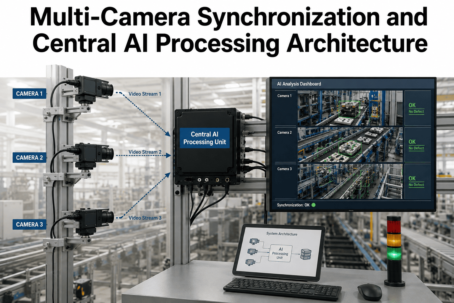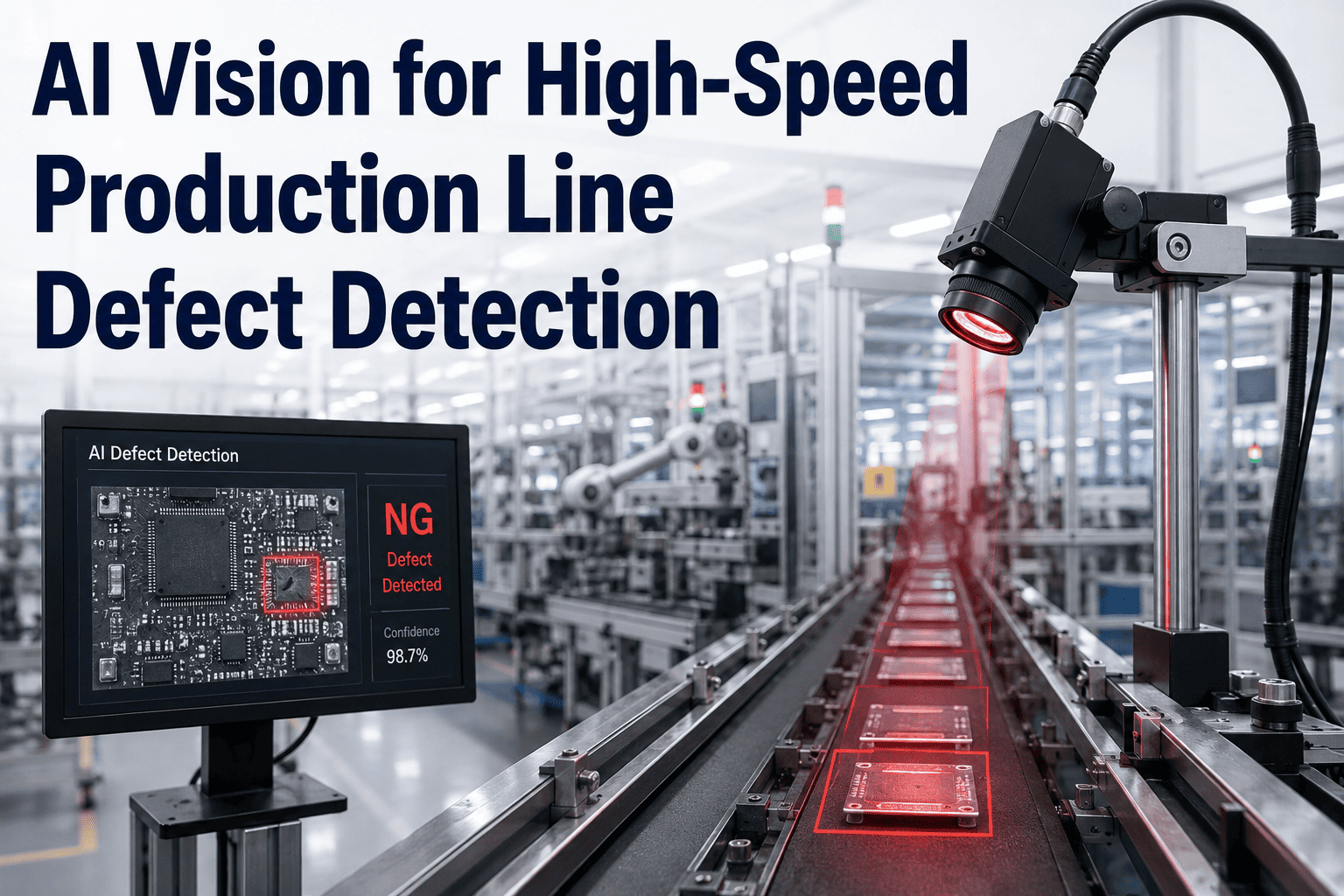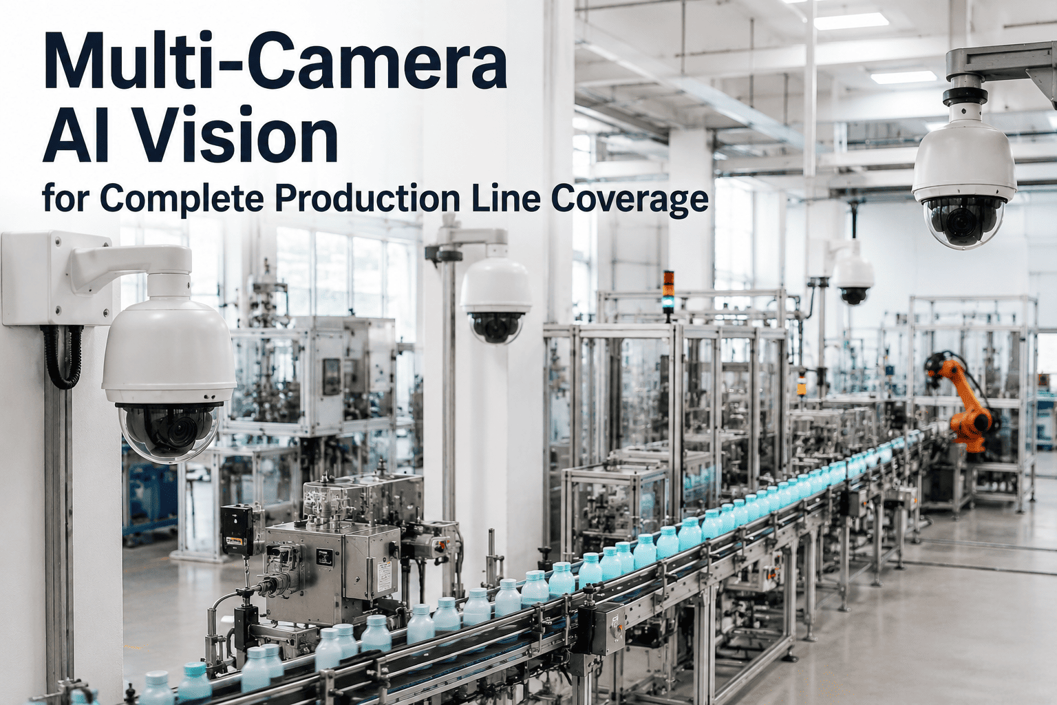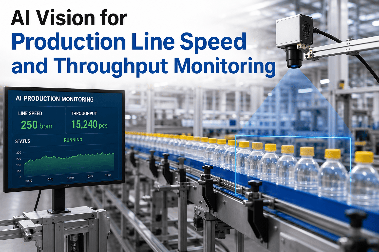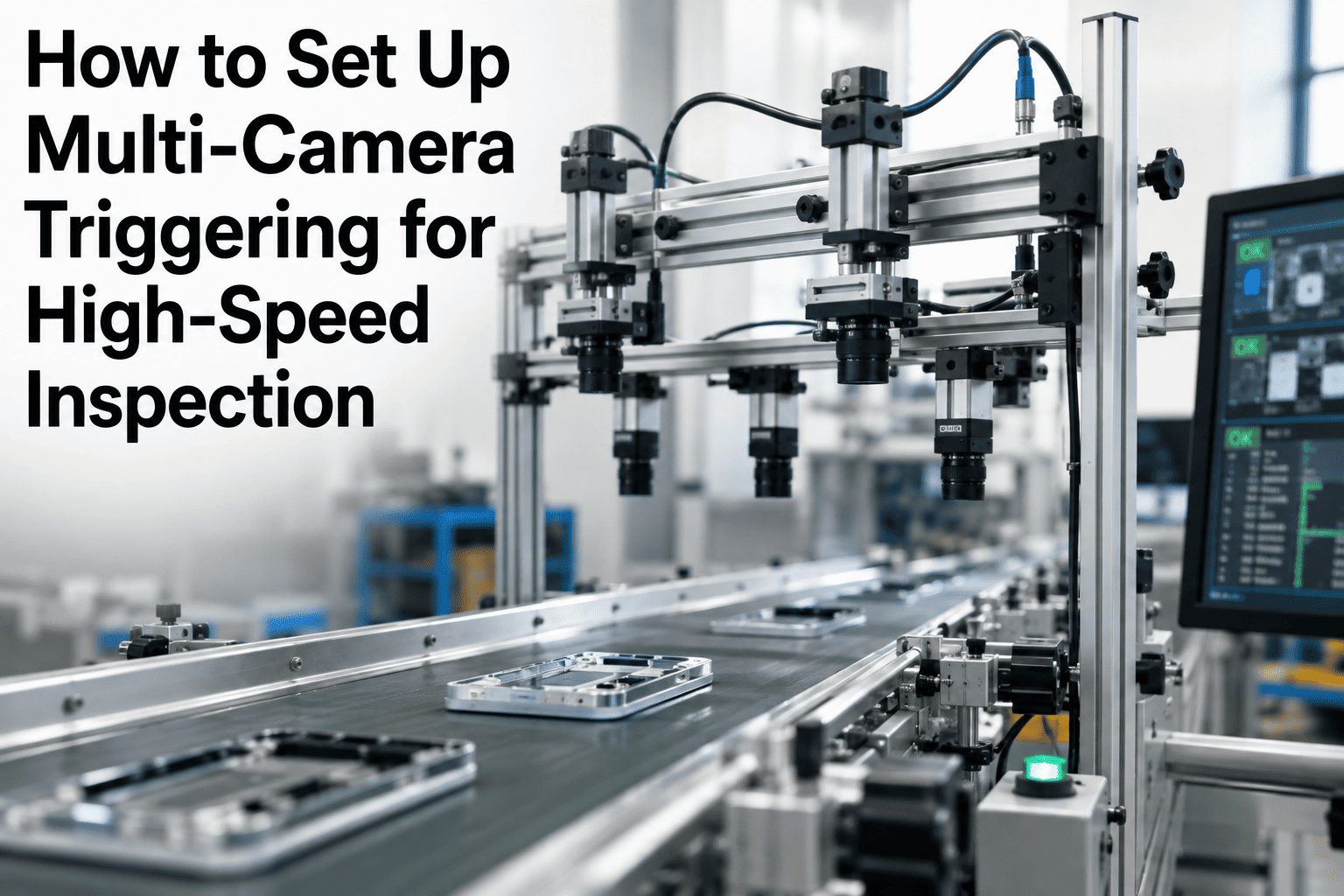
A single camera missing a part by a few milliseconds is an annoyance you fix once and forget. Four or six cameras drifting out of alignment with each other, and with the part itself, is a station that passes bad product on one angle while flagging good product on another, and the failure mode rarely announces itself cleanly. Most multi-camera inspection problems that get blamed on lighting, optics, or the AI model turn out, on inspection, to be a timing problem: the trigger reached each camera at a slightly different moment, or the encoder signal drifted against belt speed, and every downstream decision inherited that error. Getting the trigger chain right the first time is the difference between a station that runs untouched for years and one that needs a technician every shift, which is exactly the kind of build our integration engineers walk through on every multi-camera deployment.
How to Set Up Multi-Camera Triggering for High-Speed Inspection
Hardware triggers, encoder-based timing, and software synchronization, configured correctly, so every camera captures the exact same instant on a moving line.
Why This Is Harder Than Wiring One Camera
A single camera on a fixed part only has to answer one question: is the part in position when the shutter opens. Add a second camera looking at a different angle of the same part, and you introduce a second question that most integrators do not think about until it bites them: did both cameras open their shutters at the same instant, or close enough that the part had not moved measurably between the two exposures. On a stationary part this barely matters. On a part moving at production line speed, a few microseconds of misalignment between cameras translates directly into pixels of positional error between views, and once that error exceeds the tolerance your inspection algorithm needs, results start correlating poorly between angles for reasons that look nothing like a timing problem from the operator's chair.
This is the core reason multi-camera stations fail differently than single-camera ones. A single camera with a bad trigger produces obviously blurred or mistimed images that are easy to spot in a log review. A multi-camera station with a small synchronization error produces images that each look individually fine, but whose relationship to each other is subtly wrong, which shows up as inconsistent classification, occasional false rejects that nobody can reproduce, and a debugging session that starts by suspecting the model when the actual fault sits in the trigger distribution wiring.
The Trigger Chain, Start to Finish
Every setup decision covered in this guide exists to keep step three true, that every camera in the station opens its shutter at the same instant, regardless of cable length, camera count, or line speed.
Three Ways to Trigger a Camera, and When Each One Belongs
Before wiring anything, the triggering method has to match the application, because the wrong choice here cannot be fixed later with software tuning. The three approaches below cover the overwhelming majority of industrial inspection stations, and most multi-camera builds end up combining two of them, an external event trigger to fire the station and an encoder to time individual line-scan captures within it.
Free-Running Capture
The camera captures continuously at a fixed rate with no external trigger at all. This is acceptable only for stationary parts or applications where the exact capture instant genuinely does not matter. On any moving line, free-running capture means the shutter opens at an arbitrary point in the part's travel, producing inconsistent part position frame to frame. Treat this as the default to avoid, not the default to start from.
Hardware Event Trigger
A photoelectric sensor, proximity switch, or PLC output signal fires the moment a part reaches the inspection point, and that electrical pulse is distributed to every camera in the station simultaneously. This is the standard approach for discrete parts moving on a conveyor, and it is the method this guide focuses on for multi-camera synchronization, since it gives every camera the same, precisely timed starting signal.
Encoder-Based Timing
A rotary encoder mounted on the conveyor drive shaft outputs pulses tied directly to belt travel distance rather than elapsed time, which means camera timing tracks actual material movement even when line speed varies. This is essential for line scan cameras building a continuous image of moving material, and it is commonly layered on top of a hardware event trigger in multi-camera area scan stations to keep frame timing locked to physical position rather than a fixed clock.
Step-by-Step: Wiring the Trigger Distribution
The physical wiring topology is where most synchronization problems originate, and it is also the easiest stage to get right if you follow one rule strictly: every camera receives its trigger from the same distribution point, never from a chain of camera to camera. The steps below walk through building that distribution correctly.
Choose the Trigger Source
Select a photoelectric sensor, proximity sensor, or PLC digital output positioned to fire reliably at the exact point you want the part inspected. Avoid taking the trigger straight from a PLC digital output if precise timing matters, since PLC scan cycles introduce jitter in the range of one to five milliseconds, which is large compared to the sub-millisecond precision cameras themselves are capable of.
Route Through a Dedicated Distribution Board
Feed the trigger signal into a dedicated trigger distribution board rather than daisy-chaining the signal from one camera's output to the next camera's input. Daisy-chaining accumulates propagation delay at every hop, and with four or more cameras that accumulated delay is often enough to break synchronization on a fast-moving line. A distribution board fans the same signal out to every camera from a single point, with equal cable length to each.
Match Cable Length and Use Optical Isolation
Keep trigger cable runs to each camera as close to equal length as the physical layout allows, since signal propagation delay scales with cable length and mismatched runs reintroduce the timing spread you are trying to eliminate. Use optically isolated trigger inputs, standard on most industrial cameras, to protect the timing signal from electrical noise generated by nearby motors, drives, and welding equipment on the factory floor.
Confirm Edge Polarity Matches Across Cameras
Set every camera to trigger on the same signal edge, rising or falling, consistently. A mismatched edge polarity between cameras produces a fixed, repeatable offset between them rather than random jitter, which is a useful diagnostic signal: if two cameras are consistently one signal transition apart rather than randomly misaligned, check polarity settings before suspecting a wiring fault.
Verify With an Oscilloscope Before Trusting Software Logs
Before relying on camera timestamps or software logs to confirm synchronization, put a scope on the trigger lines at each camera and confirm the pulse arrives within your required tolerance window. Software-reported timestamps are influenced by interrupt latency and processing delay on the receiving computer and are not a reliable substitute for measuring the actual electrical signal at the point it reaches the camera.
Get a Trigger Architecture Review Before You Wire It
Send us your station layout, camera count, and line speed, and iFactory's integration engineers will review the trigger distribution design before you commit to wiring, catching the daisy-chain and cable-length mistakes that are expensive to unwind after installation.
The Synchronization Tiers, From Basic to Precision
Not every application needs nanosecond-level precision, and over-specifying synchronization hardware wastes budget on tolerance you will never use. The table below lays out the three practical tiers of synchronization accuracy, what technology achieves each, and the line speeds and applications where each tier is actually sufficient.
| Synchronization Tier | Typical Accuracy | Technology Used | Suitable For |
|---|---|---|---|
| Basic hardware trigger | 1 to 10 microseconds | Shared trigger line from a single distribution point, matched cable lengths | Most discrete part inspection at conventional conveyor speeds |
| Encoder-referenced trigger | Sub-millimeter positional accuracy | Quadrature encoder pulses tied to physical belt travel distance | Line scan imaging and any application where line speed varies |
| PTP network synchronization | Around 100 nanoseconds | IEEE 1588 Precision Time Protocol across a PTP grandmaster clock | High-speed multi-camera stations, stereo vision, distributed camera networks |
A useful way to reason about which tier you need is to convert timing error into positional error at your actual line speed. At one meter per second of belt travel, a ten microsecond trigger spread between cameras corresponds to roughly ten micrometers of positional uncertainty between views, which is negligible for the large majority of inspection tasks. Basic hardware triggering, done correctly with a proper distribution board, is sufficient for most stations. PTP-level synchronization earns its added complexity specifically when line speeds are very high, when cameras must correlate at sub-pixel precision, or when trigger wiring across a large station becomes impractical and network-based timing distribution is the more practical path.
Setting Up PTP Synchronization for High-Speed Stations
When basic hardware triggering is not precise enough, IEEE 1588 Precision Time Protocol synchronizes every camera, frame grabber, and lighting controller in the station to a common clock reference, typically achieving accuracy in the range of a hundred nanoseconds across the entire network. Unlike a hardware trigger line, PTP does not fire a signal spontaneously in real time, it schedules cameras to capture simultaneously at an agreed future instant, which changes how the trigger event itself is initiated even though the underlying benefit, every camera capturing the same moment, is the same goal as hardware triggering.
A PTP Grandmaster Clock
One device on the network is designated the timing reference that every other device synchronizes against. This is typically a dedicated timing appliance or a switch with grandmaster capability, specified into the network architecture at the design stage rather than added afterward.
PTP-Capable Cameras
Not every GigE Vision or CoaXPress camera supports PTP natively, so this needs to be confirmed at the specification stage. Retrofitting PTP onto cameras that do not support it means a hardware swap, not a firmware update, so verify this before purchase order rather than after installation.
A Managed Network Switch
PTP timing accuracy depends on the network path between grandmaster and cameras behaving predictably. Unmanaged switches introduce variable latency that degrades synchronization accuracy, so a managed switch with PTP transparency or boundary clock support is standard for any serious deployment.
Traffic Segmentation
Vision traffic, particularly large image transfers, should sit on a dedicated VLAN separate from time-critical control traffic. Mixing high-bandwidth image data with PTP timing messages on a shared, unmanaged network is one of the most common causes of synchronization degrading after a station passes its initial commissioning test.
Budgeting the Timing Window, Millisecond by Millisecond
Every inspection cycle consumes a fixed amount of time between the part arriving and the reject decision reaching the actuator, and at high line speed that entire window can be a small fraction of a second. Mapping out where that time actually goes is what tells you whether your station has margin to spare or is running dangerously close to missing parts. The breakdown below is illustrative of a typical high-speed station and the proportions will shift with your specific hardware, but the sequence and the discipline of measuring each stage individually applies universally.
Trigger distribution itself is almost never the bottleneck once wired correctly, it is the smallest slice of the total cycle. The inference and network transfer stages are where most of the time budget goes, which is exactly where a poorly optimized model or an undersized network can quietly erase the timing margin your trigger design worked so hard to establish.
Camera Layout Patterns for Common Multi-Angle Stations
The trigger architecture has to match the physical camera arrangement, and different inspection goals call for genuinely different layouts. The three patterns below cover the large majority of multi-camera stations you will encounter, and each one has a specific synchronization consideration worth planning for before installation rather than after.
Top and Side Pair
Two cameras, one overhead and one at an angle, capturing complementary views of the same part on the same trigger event. The simplest multi-camera pattern and the easiest to synchronize correctly, since both cameras share one trigger source at a fixed cable length.
360-Degree Ring
Four to eight cameras arranged radially around the inspection point, each capturing a different rotational angle simultaneously. Cable length matching from the distribution point to each camera position becomes more demanding as camera count increases around the ring, making a dedicated distribution board essential rather than optional.
Sequential Multi-Station
Separate camera stations positioned at different points along the line, each triggered independently as the part passes. These do not require synchronization with each other, only internal consistency at each station, but do require careful part tracking so that results from different stations correlate to the correct individual part downstream.
Diagnosing Synchronization Problems After Installation
A station that passed commissioning can still develop synchronization problems weeks or months later, usually from mechanical wear, a changed line speed, or a component swapped without matching the original specification. The troubleshooting sequence below reflects the order most integrators find fastest, starting with the cheapest check and escalating only when needed.
Results are inconsistent between cameras on the same part, with no obvious pattern
Scope the trigger line at each camera individually. Random jitter across cameras, rather than a consistent offset, usually points to electrical noise on an unshielded or non-isolated trigger cable, or to a shared trigger line running too close to a variable frequency drive.
One camera is consistently offset from the others by a fixed, repeatable amount
Compare trigger edge polarity settings across all cameras, and check whether that specific camera's trigger cable was run through the same distribution board or was accidentally daisy-chained from an adjacent camera during a past repair.
Synchronization was fine at commissioning but has drifted since
Confirm line speed has not changed since the encoder or trigger sensor was calibrated, and inspect the encoder coupling for mechanical slip, a common failure mode after months of continuous vibration on a production line.
Everything looks correctly wired but images still show partial motion blur on fast parts
This is frequently an exposure time problem rather than a trigger timing problem. Confirm strobed lighting is firing in sync with the trigger and that exposure duration is short enough for the part's actual travel speed during the shutter window.
Frequently Asked Questions
Do I need PTP synchronization, or is a basic hardware trigger enough for my line?
For the majority of discrete part inspection at conventional conveyor speeds, a correctly wired basic hardware trigger, distributed from a single point with matched cable lengths, delivers accuracy in the low microsecond range, which translates to a few micrometers of positional uncertainty even at a meter per second of line travel. That level of precision is more than sufficient for most quality inspection tasks. PTP earns its additional complexity specifically at very high line speeds, when cameras must correlate at sub-pixel accuracy for tasks like stereo vision or precision measurement, or when the physical distances involved make trigger cable wiring genuinely impractical. Reviewing your specific line speed and tolerance requirements with an integration engineer is the fastest way to confirm which tier actually applies to your station.
Can I trigger my cameras directly from a PLC digital output?
You can, but it introduces more timing uncertainty than most high-speed applications can tolerate. PLC scan cycles typically introduce one to five milliseconds of jitter into the trigger signal, which is a large window compared to the sub-millisecond precision industrial cameras are capable of achieving. For applications where timing precision genuinely matters, route the trigger through a dedicated sensor and distribution board instead, and use the PLC only to receive the inspection result after the fact, not to generate the capture trigger itself.
Why is daisy-chaining trigger cables between cameras a problem if the delay is so small?
Each hop in a daisy chain adds its own propagation delay, and while a single hop might only add a fraction of a microsecond, that delay accumulates linearly with camera count. On a four-camera station the accumulated offset between the first and last camera in the chain can become large enough to matter at production line speeds, and the effect gets worse as you add cameras rather than staying constant. A dedicated distribution board delivers the same signal to every camera from a single point simultaneously, which keeps the accumulated delay problem from existing in the first place regardless of how many cameras the station eventually grows to include.
How do I know if a synchronization problem is causing my inconsistent inspection results?
Review the inspection log for patterns first: failures that cluster at a specific camera, a specific part orientation, or a specific time of day often point to a timing or hardware issue rather than a model accuracy issue. Run a set of known-good and known-defective sample parts through the station and compare current results against your originally validated baseline settings, since a documented baseline is what makes this comparison possible at all. If results have drifted from that baseline with no software or model changes in between, the trigger chain and encoder calibration are the first places to check before questioning the inspection algorithm itself.
What is the single most common mistake in multi-camera trigger setups?
Daisy-chaining trigger signals from camera to camera instead of using a dedicated distribution board with matched cable lengths from a single source point. It is the most common mistake because it often works acceptably during initial commissioning at conservative line speeds, then produces intermittent, hard-to-reproduce inconsistencies once the line speeds up or a camera is added later. A close second is taking the trigger directly from a PLC output rather than a dedicated sensor, which introduces avoidable scan-cycle jitter into a signal that should be as clean and immediate as possible. Both mistakes are inexpensive to avoid at design time and expensive to diagnose after the station is already running production, which is exactly why a design review before wiring, something our integration team offers on every project, consistently pays for itself.
Build the Trigger Architecture Right the First Time
A poorly wired trigger chain produces failures that look like model problems, lighting problems, or mechanical problems, and none of the obvious fixes work. iFactory's integration engineers design and validate multi-camera trigger distribution, encoder timing, and PTP synchronization before your station ever runs its first part.