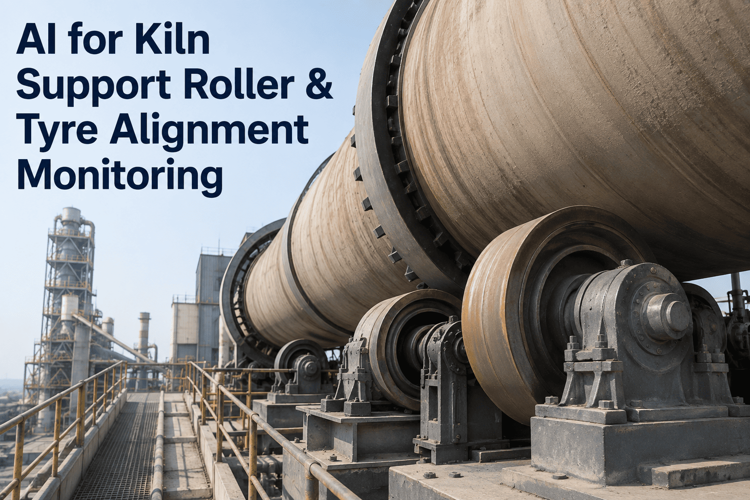
A rotary cement kiln is a 2,000-tonne tube spinning under a shell surface temperature above 400°C, carried entirely by a handful of support rollers and riding tyres. When one of those rollers drifts a degree or two out of alignment, no one standing next to the kiln can see or feel it — but every single rotation compounds the error, gradually distorting how load is distributed until the shell itself deforms into an oval cross-section. By the time ovality is visible, the kiln has often been running under abnormal stress for months, and the fix has escalated from a simple roller adjustment to a shell repair. The problem with catching it is timing: traditional hot-kiln alignment surveys happen every 3 to 6 months, leaving long blind windows where drift progresses unseen. Continuous AI monitoring closes that window — tracking shell ovality, support-roller thrust, and tyre-shell gap in real time so intervention happens while it's still cheap. If your last alignment survey is more than a quarter old, book a demo to see what's happening to your kiln axis right now.
Your Kiln Is Drifting Between Surveys. AI Is the Only Thing Watching in Between.
Support-roller skew, tyre creep, and shell ovality develop gradually — invisible to a walk-around, invisible until the next contractor survey months from now. iFactory's AI tracks all three continuously against a live digital twin, flagging axis deviation while correction is still a roller tweak, not a shell rebuild. It's the layer of visibility that turns kiln alignment from a scheduled event into an always-on discipline.
Why Alignment Failures Stay Invisible Until They're Expensive
Kiln misalignment almost never appears overnight. It develops gradually through thermal cycling, foundation settlement, and component wear — and stays completely invisible until product quality drops or a major component fails. A misalignment of a single degree isn't something a technician can reliably detect by standing beside a rotating kiln, yet that small deviation shifts how load transfers across the roller face with every rotation. What begins as a slight bearing-clearance change or a small pier settlement compounds silently, producing a flat spot on the roller, accelerating tyre wear, and eventually distorting the shell into an oval cross-section far more expensive to correct than the original misalignment ever was.
The reason this matters so much on a kiln specifically is the scale of what's rotating. A typical cement rotary kiln runs 75 to 80 metres long, occasionally reaching 150 metres, with diameters up to 6.5 metres, carrying thousands of tonnes of steel, refractory, and material. Straightness deviations of that axis — caused by installation tolerances, bearing-ring wear, roller wear, and foundation movement — exert dynamic bending stress on the shell with every single revolution. At operating speed, that's thousands of stress cycles per shift working on a deviation nobody has measured since the last survey. The physics guarantee that small drift becomes large damage; the only variable is whether anyone sees it coming.
The Interval Survey Was Never Built for Continuous Drift
Hot-kiln alignment surveys — measuring kiln axis, shell crank, and roller positions while the kiln runs at temperature — are traditionally performed on an interval basis by specialized contractors every 3 to 6 months, and sometimes only every 6 to 18 months. Each survey is a single high-quality snapshot. But drift doesn't wait for the snapshot. Between two surveys, a roller can skew, a pier can settle, and a tyre can migrate meaningfully — and the plant runs blind through all of it, responding to symptoms rather than signatures because there's no trend data connecting one measurement to the next.
Continuous monitoring doesn't replace the value of an expert alignment survey — it makes each one far more useful, because the AI has already tracked exactly what changed since the last one and can point the contractor straight at the station that moved. The snapshot becomes the confirmation of a trend the plant has been watching, not the first time anyone learns something shifted.
What iFactory's AI Actually Watches, Station by Station
iFactory's kiln mechanical analytics doesn't require ripping out existing instrumentation. Most cement plants already have infrared shell scanners, thermocouple arrays, bearing sensors, and drive monitoring — but the data sits siloed in separate displays with no integration and no correlation. The AI ingests these existing streams, adds continuous ovality and thrust measurement where gaps exist, and correlates everything against a physics-based digital twin of the kiln to distinguish real geometric drift from normal thermal behavior. The result is that four mechanical signals, each meaningless in isolation, become a single coherent picture of how the kiln's geometry is actually changing.
Continuous ovality measurement correlated against tyre migration, thermal conditions, and machine-learned anomaly patterns. Rather than reporting a single "ovality is high" flag, the system distinguishes between the distinct root causes — worn tyre support pads, excessive tyre elevation, dogleg conditions — so the corrective action is targeted rather than a generic tyre adjustment that may not address the real driver.
Vibration, temperature, and axial position tracked together across every support station simultaneously. Because misalignment and lubrication degradation show up in the relationship between these signals — not any one of them alone — the AI catches a roller working against the axis while the correction is still a simple skew adjustment, long before it becomes uneven shell loading.
Tyre creep — the relative movement between riding tyre and shell — is most damaging during heat-up and cool-down when thermal stress peaks and the kiln turns below 0.1 RPM. Continuous monitoring captures these critical transition events that periodic manual measurement misses entirely, trending creep rate against its safe window and flagging the day it starts climbing toward the intervention threshold.
The thrust roller controls the kiln's axial position and prevents it from creeping along its own centerline. Its wear pattern is easy to miss on a routine walk-around, so the AI trends bearing load and axial-movement sensor data continuously, catching thrust-roller misalignment before it generates the axial forces that create shell crank — eccentricity between the rotation axis and shell centerline.
See Live Roller Condition Mapped to a Real Support Station
Bring your last alignment survey and your kiln's support-station layout to the call. iFactory engineers will show how continuous ovality, thrust, and creep monitoring would map onto your specific kiln, and what the trend view reveals between your scheduled surveys.
How the Digital Twin Turns Signals Into Decisions
Raw sensor data alone doesn't tell a reliability engineer whether a rising ovality reading means a genuine problem or just a hotter-than-usual operating day. The digital twin is what converts signals into decisions — a physics-based model of the kiln's mechanical geometry that knows what the shell, tyres, and rollers should be doing under any given thermal and load condition, so a real deviation stands out from normal variation.
The Economics of Catching Drift Early
The financial case for continuous alignment monitoring isn't abstract — it's the enormous gap between the cost of a roller adjustment and the cost of the shell repair that same drift becomes if left unwatched. The kiln is the single most consequential asset in the plant, operating at 1,450°C for well over 300 days a year, and its unplanned failures are the most expensive events a cement producer faces. The four-stage ladder below is the same physical drift measured at four different points in its life — and the cost multiplies by orders of magnitude at every step down.
Kiln and pyroprocessing failures account for roughly a third of all unplanned downtime in cement plants, and alignment-driven shell and refractory problems sit near the top of that list. Every one of them starts as the kind of slow geometric drift that continuous monitoring is designed to catch in its earliest, cheapest stage — the difference between an adjustment logged in a maintenance window and an emergency that costs more than an entire year's preventive maintenance budget. Industry experience is consistent on this point: plants running structured, digital kiln monitoring drop kiln-related downtime from the 3 to 5 percent of annual clinker capacity typical of paper-based programs to below 1 percent. That gap is almost entirely made up of failures that gave warning signs no one was positioned to see.
How Deployment Works on a Running Kiln
Continuous alignment monitoring is designed to layer onto an operating kiln without a shutdown, using the instrumentation most plants already have and adding only what's genuinely missing. The rollout below reflects how a typical cement plant moves from interval-only surveys to always-on alignment intelligence, and because it builds on existing sensors, the timeline is a data-integration effort rather than a capital-equipment project.
Frequently Asked Questions
The questions reliability and mechanical engineers ask most often before adding continuous alignment monitoring to their kiln.
Watch Your Kiln Axis Continuously — Not Once a Quarter.
Turn siloed shell, bearing, and drive data into a live alignment trend backed by a physics-based digital twin. Catch support-roller skew, tyre creep, and shell ovality while the correction is still a simple adjustment — long before it forces a stop, distorts the shell, or turns your next survey into an emergency.