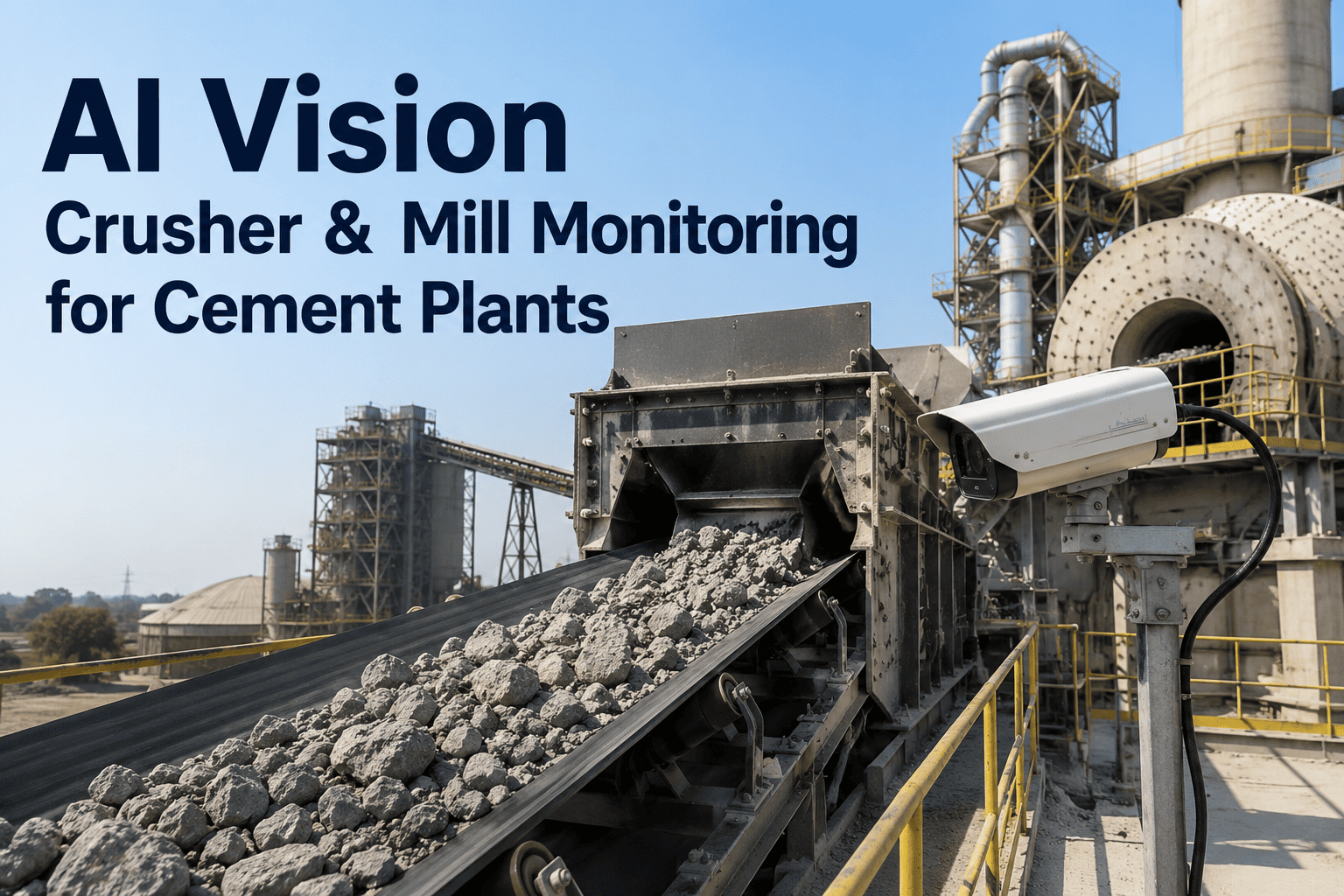
Every cement plant already has cameras pointed at the crusher house. Most of them are useless for detection, and not because the hardware is bad — because nobody can see through the dust. A limestone crushing circuit generates airborne particulate dense enough that an operator watching a monitor sees a grey rectangle, which is exactly why blockages get discovered by a torque trip rather than by anyone looking. Vision only becomes useful here when the model is trained on degraded imagery rather than clean imagery, and you can book a demo to see detection running on footage from your own crusher house.
CRUSHER AND MILL MONITORING · VISION ANOMALY DETECTION · EDGE AI
See Oversized Rock, Tramp Metal and Chute Buildup Through the Dust
iFactory runs deep learning models trained specifically on cement plant conditions — heavy particulate, heat shimmer, vibration and low light — so oversized material, foreign objects and developing buildup are caught at the feed point instead of at the crusher throat.
60 inches
Rock size that jams primary crushers
$10-25K
Per hour of unplanned cement downtime
Up to $300K
Cost of a single day of plant downtime
Sub-second
Capture to stop request at the edge
The Visibility Problem
What a Human Cannot See and a Model Still Can
The crusher house is close to the worst imaging environment in heavy industry. Airborne limestone dust scatters light in every direction, heat shimmer distorts geometry near hot equipment, structural vibration blurs frames, and lighting swings between blown-out daylight at an open feed point and near-darkness inside a chute. A general-purpose object detection model trained on clean imagery collapses under those conditions, which is the real reason so many plants concluded that vision does not work here.
The distinction that matters is between what an image looks like and what an image contains. A human observer needs recognisable contrast and edges to identify an object; a model trained on this specific degradation works from statistical structure that survives conditions where recognisability does not. The four rows below set out that gap directly, because it is the single most common objection raised in the first meeting.
Same Frame, Two Different Readings
Heavy dust plume at the feed point
What the operator sees
A uniformly grey field with no usable detail. Watching this monitor for oversized material is not a task a person can perform, which is why nobody actually does it.
What the model extracts
Residual edge structure and motion differential between the material stream and the dust cloud, which move at different rates and separate statistically even when they do not separate visually.
Heat shimmer near hot surfaces
What the operator sees
Distorted, rippling geometry that makes size judgement unreliable and makes a stationary object appear to move.
What the model extracts
Shimmer is periodic and spatially bounded. Averaging across consecutive frames separates the optical distortion from genuine object motion, since real material travels in one direction and shimmer oscillates.
Extreme lighting range across one scene
What the operator sees
A blown-out bright zone at the open feed opening and a near-black chute interior in the same frame, with no exposure that serves both.
What the model extracts
Synchronised LED arrays hold illumination independent of ambient conditions, and the model is trained across the full exposure range rather than a single lighting condition, so both zones remain analysable.
Progressive lens contamination
What the operator sees
Nothing at all, until a maintenance round notices the feed has been useless for a fortnight. This is the most common silent failure of camera systems in cement.
What the model extracts
Image quality is monitored as a signal in its own right, so degradation raises a cleaning task before detection confidence falls. Automated lens cleaning is standard where particulate loading is heaviest.
The fourth row is the one that decides whether a system is still working a year after commissioning. A detection model that does not monitor its own input quality will fail silently and confidently, which is worse than not being installed.
This also explains why models trained on generic industrial datasets underperform badly in this application. Detection accuracy in a crusher house depends less on the sophistication of the architecture than on whether the training data contains thousands of hours of the specific degradation that plant produces. Dust density varies with material moisture, season, and feed rate; heat shimmer depends on equipment layout; vibration signature depends on mounting. Calibration on site is not a tuning step at the end — it is most of the work.
Detection Targets
Four Things Worth Watching For, and What Each Costs When Missed
A vision system earns its place by catching a small number of high-consequence conditions reliably, not by classifying everything. In a crushing and grinding circuit those conditions are well established, and three of the four are invisible to the magnetic and process instrumentation the plant already has. The costs attached below are drawn from published cement downtime figures rather than modelled optimistically.
01
Biggest single productivity loss
Oversized Rock
Rocks larger than roughly sixty inches jam primary crushers and are cited as the largest contributor to productivity loss in the circuit. Clearing one requires isolation, lock-out, and manual breaking — hours of work for a single piece of material that could have been diverted at the feed point in seconds.
Detected by: size estimation against a calibrated reference plane on the feed belt
02
Wear parts plus cascade
Tramp Metal and Foreign Objects
Bucket teeth, mantle fragments, bar scrap, chains, and dropped tools destroy crusher wear parts on contact and can carry through to the mill. Vision catches what a magnetic loop cannot — non-ferrous items, timber, liner rubber, and broken chute plate riding on the surface of the stream.
Detected by: shape and texture classification against learned normal material
03
Progressive, then sudden
Chute and Transfer Buildup
Wet or sticky material accumulates on chute walls over hours, narrowing the aperture until flow chokes entirely. Because it develops gradually it produces no alarm until the moment it becomes a full blockage, at which point material backs up onto the belt and the stop is already unavoidable.
Detected by: aperture geometry trending frame over frame against clean baseline
Feed Starvation and Surge
Uneven feed presentation drives crusher choke-feeding problems, uneven liner wear, and throughput loss that no single alarm captures. A continuous read of bed profile and coverage across the belt width turns feed quality into a controllable variable rather than an assumption.
Detected by: material bed profile and belt coverage measured continuously
The third target is the one most operators underrate and the one where vision has the least competition. There is no sensor that meaningfully measures chute buildup — level instruments see material presence, not wall accretion, and the condition is entirely geometric. A camera looking down a chute at a clean reference geometry can trend aperture narrowing over hours, which converts a sudden choke into a scheduled wash-out during a planned stop. That is a class of problem where vision is not a better option; it is effectively the only option.
Latency Budget
From Frame Capture to Stop Request, Measured in Milliseconds
Detection is only protection if the decision completes before the object arrives. Feed belts move material at metres per second, so the entire chain from photon to stop command has to fit inside the travel time between the camera's field of view and the crusher throat. That is a hard engineering constraint, and it is the reason the analysis has to run at the edge rather than anywhere else. Book a demo to see the budget calculated against your own belt speeds and camera positions.
Typical Decision Chain at the Feed Point
Step 1
Frame Capture
Continuous capture under synchronised illumination, at a rate high enough that an object crossing the field of view appears in multiple consecutive frames rather than one.
Continuous
Step 2
Edge Inference
The detection model runs on hardware at the camera position. Nothing leaves the plant network for this step, because a round trip to a remote server would consume the entire available budget on network transit alone.
Tens of ms
Step 3
Multi-Frame Confirmation
A detection is confirmed across consecutive frames before it is acted on. This is what separates a genuine object from a dust artefact, and it is the single most important defence against nuisance stops.
Tens of ms
Step 4
Classification and Routing
The confirmed detection is classified by type and severity, which determines whether it becomes a stop request, a control room alert, or a logged maintenance finding for a planned intervention.
Single-digit ms
Step 5
Stop Request to Control System
A request is issued to the existing control system, which retains authority to act. The vision layer never commands a drive directly and holds no control function of its own.
Sub-second total
Representative budget rather than a guaranteed specification, since actual timing depends on model size, edge hardware, and control system response. The design principle is fixed: every step before the control system must complete in less time than the object needs to travel from the camera to the crusher.
Step three is where most of the practical engineering effort goes, because it governs the trade every plant actually cares about. Requiring confirmation across more frames reduces nuisance stops and increases confidence, but consumes budget and shortens the remaining travel distance. Requiring fewer frames responds faster and stops more often for things that turn out to be dust. Where that threshold is set determines whether operations trusts the system, and it is tuned per camera position rather than globally, because a feed point at an open transfer and a chute interior have completely different noise characteristics.
TEST IT ON YOUR OWN FOOTAGE
Send Us an Hour of Crusher House Video and We Will Show You What Is Detectable
Our cement team will run detection against recorded footage from your existing cameras under your real dust conditions, then show you which positions already support reliable detection and where illumination or framing is the actual constraint.
Architecture
Why This Has to Run at the Edge
The choice between edge and centralised processing is often presented as a preference. In this application it is not. Several of the constraints below are absolute rather than economic, and any architecture that fails them will not survive a plant's first network outage or its first month of video egress billing. The comparison sets out where each approach genuinely sits.
The last row is the honest resolution. Nobody serious runs a pure edge deployment with no central component, because the training loop needs examples pooled across cameras and across plants to keep improving, and a model frozen at commissioning degrades as material and conditions change. Nor does anyone stream raw video from a crusher house to a remote data centre for real-time stopping decisions. Inference happens where the camera is; learning happens where the data can be aggregated. The architectural question is only where the boundary sits, and for a stopping decision it sits at the edge without exception.
One point worth stating plainly on integration, because it comes up in every review with a plant manager. The vision layer is a software intelligence layer rather than a control system. It consumes camera feeds, produces classified detections, issues stop requests and work orders, and integrates with existing maintenance systems. It does not hold control authority over any drive, does not sit inside a safety instrumented function, and can be isolated entirely without affecting the plant's ability to run.
The Arithmetic
Twenty Seconds at the Feed Point Against Five Hours at the Throat
The economic argument does not require heroic assumptions, because the comparison is between two versions of the same event. A piece of oversized material either gets removed from a stopped belt at the feed point, or it gets removed from inside a crusher after it has jammed. The second version is not marginally worse than the first — it is a completely different category of work, involving isolation, lock-out, confined access, and manual breaking. The timeline below traces it.
Clearing a Jammed Primary Crusher, Cumulative Cost
0 to 15 min
Trip, confirm, stop upstream feed
The crusher trips on torque or power. Feed conveyors are stopped and upstream belts purged so material does not pile at the transfer while the circuit is down.
About $4,000
15 to 45 min
Isolation and lock-out
Full electrical and mechanical isolation of the crusher and its feed conveyors, with lock-out applied and verified before anyone approaches the chamber. This step cannot be compressed.
About $11,000
45 to 90 min
Access, assessment, rigging
Crew gains access under a permit, assesses how the material is wedged, and rigs lifting or breaking equipment. Confined access in a crushing chamber carries its own controls and its own pace.
About $22,000
90 to 240 min
Manual breaking and removal
The blocking material is broken down and removed piece by piece. This is the longest phase and the least predictable, since it depends entirely on how the rock has keyed itself into the chamber.
About $60,000
240 to 300 min
Liner inspection, restore, restart
Wear parts are inspected for damage, isolation is removed, and the circuit is restarted and ramped. Downstream stockpile drawdown may continue affecting raw mill feed after the crusher is back.
About $75,000
Costed at the lower end of the published range for unplanned cement downtime, around fifteen thousand dollars per hour against a range of ten to twenty-five thousand. Phase durations are representative and will vary with crusher type, access arrangement, and how the material is wedged.
The safety dimension travels alongside the cost and frequently matters more to the people signing off the investment. Clearing a jammed crushing chamber means putting people inside a confined space next to stored mechanical energy, under a permit, often at height, occasionally with hydraulic breaking equipment. Every one of those exposures is eliminated when the material never reaches the chamber. A monitoring case built purely on downtime avoidance understates what is actually being bought.
The wider figures reinforce the scale. Published cement downtime costs run to roughly three hundred thousand dollars for a single day of plant downtime, with mill and crusher circuits carrying downtime costs in the region of twenty-five to one hundred and twenty thousand dollars per day depending on asset. Against those numbers, a single prevented jam per year covers a detection deployment across the crushing circuit, which is why the argument usually turns on whether the plant believes the detection works rather than on whether the maths adds up.
Frequently Asked Questions
Crusher and Mill Vision Monitoring — Common Questions
Our crusher house is genuinely too dusty for cameras. Why would this be different?
Because the model is trained on that dust rather than in spite of it. Detection here does not depend on a human-recognisable image; it works from motion differential, residual edge structure, and multi-frame statistics that persist when visual contrast does not. Synchronised LED illumination holds lighting independent of ambient conditions, automated lens cleaning handles the heaviest particulate positions, and image quality is monitored as a signal so degradation raises a cleaning task rather than silently reducing accuracy. The fastest way to settle the question is empirical, and you can
book a demo where we run detection against your own recorded footage.
Can this use our existing cameras or does everything need replacing?
Existing cameras are usable at many positions and reusing them is normally the fastest route to a working system. The constraints that actually decide it are framing, illumination, and frame rate rather than camera brand — a camera aimed at a general area for security purposes may not be positioned to see the material stream against a calibrated reference, and belt speed sets a minimum capture rate. The assessment typically finds that several existing positions work directly, one or two need repositioning or added illumination, and only heavily contaminated locations justify new hardened hardware.
How do you stop this from tripping the circuit every time a dust cloud passes?
Multi-frame confirmation before any stop request, with the confirmation threshold tuned per camera position rather than set globally. Dust artefacts do not persist coherently across consecutive frames the way a physical object travelling on a belt does, so requiring agreement across a sequence removes the overwhelming majority of false positives. Positions are also tuned separately because an open feed point and a chute interior have entirely different noise characteristics, and most plants begin with conservative thresholds and tighten them as the accuracy record builds on their own material.
Does this replace our metal detector or our process instrumentation?
No, and it covers a different set of failures. A magnetic detector finds ferrous material buried inside a loaded belt, which a camera cannot see through. Process instrumentation reports torque, power, and level. Vision covers what neither sees — non-ferrous oversized material on the surface of the stream, chute wall buildup, which is purely geometric and has no sensor equivalent, and feed presentation quality. The strongest configurations run vision alongside existing detection so that a magnetic alert arrives with a visual frame confirming what was actually found.
Do you supply the cameras and edge hardware, or only the software?
iFactory is the AI intelligence layer rather than a sensor or camera manufacturer, so hardware is specified against the requirement and sourced from established industrial suppliers rather than sold as a proprietary package. In practice that works in the plant's favour, because camera and illumination selection can be matched to each position's real conditions and to whatever standards your site already applies for industrial equipment. Our team can walk through a position-by-position specification for your crushing and grinding circuit through
support.
IFACTORY · CEMENT · VISION ANOMALY DETECTION
Catch It on the Belt, Not in the Chamber
iFactory brings detection to the one part of a cement plant where visibility fails and consequences are highest — classifying oversized rock, foreign objects, chute buildup and feed quality at the edge, in the dust, before the crusher throat ever sees them.
4 targets
Oversize, foreign object, buildup, feed quality
Edge first
Inference on site, learning aggregated centrally
Self-checking
Image quality monitored as its own signal
No control
Requests a stop, never commands a drive