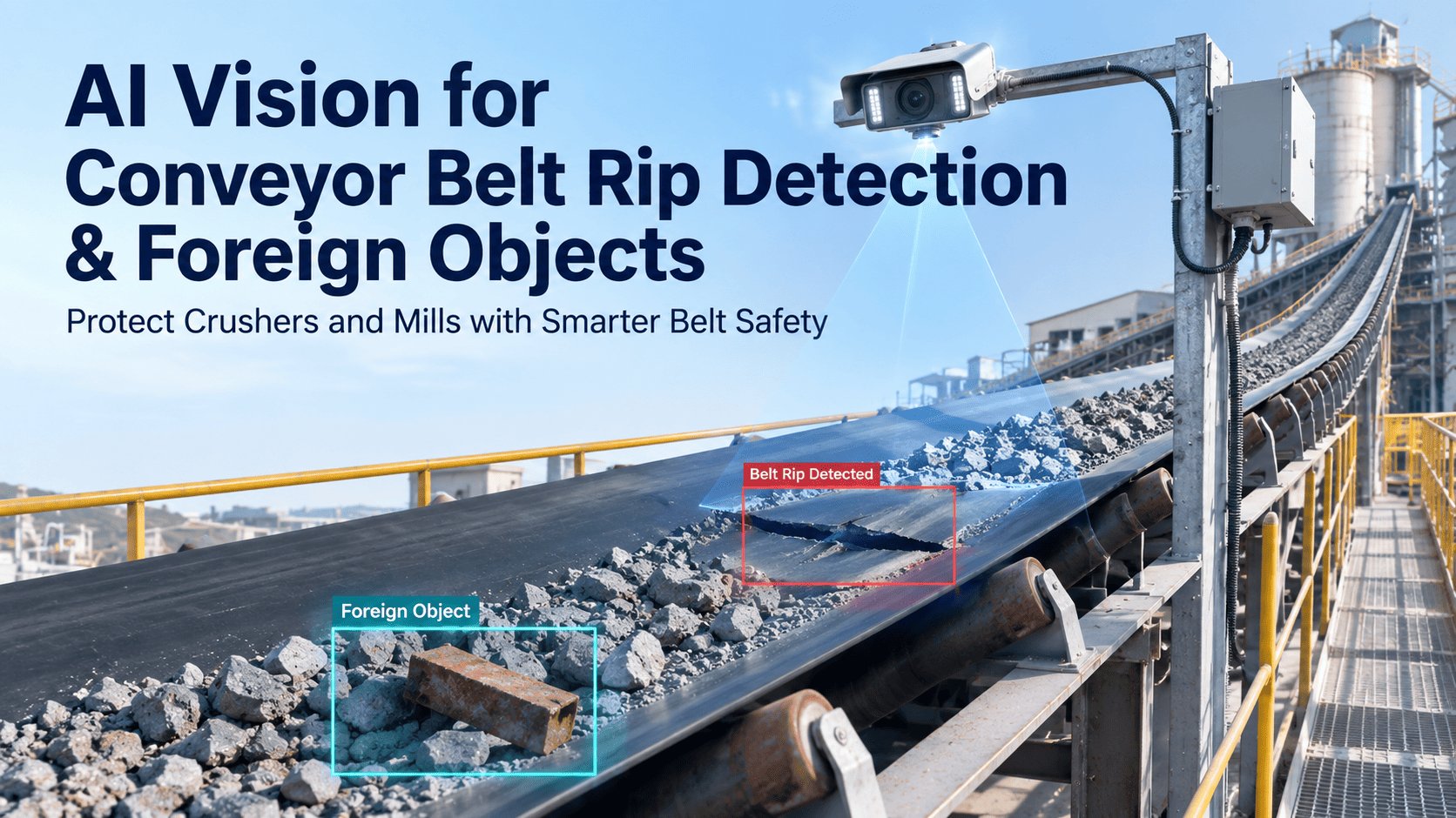
AI Vision for Conveyor Belt Rip Detection & Foreign Objects

By James C on August 13, 2026

ai-vision-conveyor-belt-rip-foreign-objects

A longitudinal rip does not start as a catastrophe. It starts as a puncture — a bucket tooth, a broken mantle segment, a length of bar scrap wedging itself between the belt and a chute wall while the belt keeps pulling. From that moment the outcome is decided entirely by how many seconds pass before the drive stops. At four metres per second, the difference between a detection in milliseconds and a detection at the next walkaround is the difference between a patch and a full belt replacement, and you can book a demo to see the detection running on your own conveyor lines.

BELT SAFETY · AI VISION CAMERA PLATFORM · FOREIGN OBJECT DETECTION
Stop the Belt in Metres, Not Kilometres
iFactory's AI vision watches every major conveyor for longitudinal rip, tramp iron, oversized rock, chute blockage, and belt misalignment — classifying the fault in under 200 milliseconds and triggering the stop before the damage propagates or reaches the crusher.
Under 200ms
Object detection and classification

1-2 m
Rip length contained with e-stop

$15,000
Crusher heads destroyed in seconds

4-6 weeks
Priority lines live, no production stop
The Propagation Clock

Every Second of Detection Delay Is Measured in Metres of Belt

Raw material conveyors in a cement plant run at roughly 2 to 5 metres per second, carrying chunks up to 1.2 metres across before the primary crusher. When a sharp object wedges against the belt carcass, the belt is driven forcibly past the obstruction and the tear extends at close to belt speed. This is why rip detection is uniquely unforgiving compared to almost every other fault type in the plant — there is no degradation curve to trend, no weeks of warning. There is only how quickly the drive stops.

Rip Length at the Moment of Detection
AI vision with automatic stop

1-2 m
Documented field case, plate impact

12 m
Overnight tear found at morning round

3 m and growing
No detection, belt runs to failure

Full belt
Bars are scaled for legibility rather than drawn to true proportion. The final case is the one that determines whether the repair is a patch, a section replacement, or a new belt — and a rip that runs the belt length can take up to 48 hours to put right.

The documented case behind the second bar is worth reading closely because it reflects exactly how these events happen. A steel plate came loose from a primary crusher and fell onto the main production belt at a cement operation. The detection system stopped the belt within twelve metres of the impact point, and the operator's own assessment was that without it, the belt would have ripped completely in half. With typical rip repairs taking up to 48 hours and downtime costed at around 20,000 pounds per hour, that single detection event was valued at between 700,000 and 800,000 pounds in avoided production loss and repair cost.

The third bar describes the quieter version of the same failure. A hairline longitudinal tear forming on the return side at two in the morning will grow for six hours before a morning walkaround finds it, by which point the damage has extended several metres and patch repair is no longer an option. Nothing about that scenario involves a dramatic impact or an obvious event. It simply requires that nobody was looking at the belt for six hours, which describes the normal operating condition of almost every conveyor in the industry.

Fault Taxonomy

Six Fault Classes, Six Different Urgencies

Not all belt damage carries the same clock. A surface scratch has days of lead time and belongs in the routine work queue. An active longitudinal tear near a splice joint can propagate to full belt failure in under an hour at operating speed and belongs on an emergency stop. A detection system that treats every finding as equally urgent produces alert fatigue within a fortnight, and one that treats them as equally routine produces a destroyed belt. Classification is therefore not a nice-to-have on top of detection — it is what makes detection actionable.

Active longitudinal rip
Immediate stop

Propagates at close to belt speed and can reach full belt failure within the hour. The only correct response is an automatic drive stop, with human review after the belt is stationary rather than before.
Tramp iron and foreign metal
Immediate stop

Bucket teeth, manganese mantle fragments, bore crowns, bar scrap, chains, and dropped hand tools. Destroys crusher wear parts on contact and can initiate a rip at any wedge point on the way there.
Chute and transfer blockage
Minutes

Material bridging at a transfer point backs product onto the belt, causing spillage, belt overload, and in the worst case a belt pressing against structural steel until it burns through.
Oversized rock and rogue material
Minutes

Non-metallic and therefore invisible to a magnetic detector. Blocks chutes, jams crusher inlets, and is a common trigger for the wedging events that start longitudinal tears.
Belt misalignment and edge damage
Hours

Tracking drift causes progressive edge wear and spillage. Detectable well before it becomes structural, and one of the highest-value routine findings because it is entirely preventable.
Surface cracking and splice wear
Days

Frame-by-frame surface analysis tracks crack width and propagation rate on both carrying and return sides, converting splice condition into a planned replacement date rather than a surprise.

The fourth class carries a specific point that decides most technology comparisons. Oversized rock, timber, rubber liner fragments, and broken chute plate are all non-ferrous, which means a magnetic tramp metal detector will pass them straight through to the crusher without registering anything. In cement operations the material stream naturally contains large limestone chunks, and the distinction between an ordinary large rock and one that will jam the crusher inlet is a size and shape judgement — exactly the kind of judgement a trained vision model makes and a metal detector structurally cannot.

Camera Placement

Where the Cameras Go and What Each Position Is For

Most cement plants already have cameras above their major conveyor lines. The problem is rarely visibility — it is that those cameras record everything and analyse nothing, so footage becomes forensic evidence after the event rather than a control input during it. Converting an existing camera estate into a detection system is largely a matter of putting the right analysis on the right position, because each point along a conveyor run answers a different question. Book a demo to map this against your own line layout.

Detection Stations Along a Raw Material Conveyor Run
01
Feed and Loading Point
The single highest-value position. Foreign objects enter the system here, and catching them at the load point means they never travel toward a crusher or a wedge point at all.
Watches for: tramp iron, oversized rock, timber, impact damage
02
Carrying Side Mid-Span
Continuous surface analysis of the loaded belt for tears developing under material cover, plus tracking drift that would otherwise only be caught by a walkaround.
Watches for: rip propagation, misalignment, load profile
03
Return Side After Discharge
The only place the belt surface is fully visible without material on it. Hairline cracks, splice condition, and small punctures show clearly here and nowhere else on the run.
Watches for: surface cracking, splice wear, small punctures
04
Transfer Chute Approach
Where wedging events begin. A jammed object at a chute lip is the classic rip initiator, and blockage build-up is visible here well before it backs material onto the belt.
Watches for: blockage, bridging, wedged objects
05
Crusher and Mill Inlet
The last line of defence before an object meets rotating steel. A stop triggered here still costs a restart, but it saves the wear parts and the hours that follow their destruction.
Watches for: anything that got past stations 01 to 04
Station 03 is the one most plants overlook. The carrying side is where cameras are naturally mounted, but the belt surface there is covered in material, so the fault that is easiest to fix cheaply is also the one nobody can see.

Station five deserves an honest framing. Detecting an object at the crusher inlet is a genuine save, but it is the least valuable of the five because the stop is already unavoidable at that point and the belt has carried the hazard across its full run. The whole design intent of a multi-station approach is to push detection as far upstream as possible, so that the majority of interventions happen at the loading point where the response is simply removing an object from a stationary belt rather than an emergency stop that ripples through kiln feed.

USE THE CAMERAS YOU ALREADY HAVE
Turn Your Existing Conveyor Camera Estate Into a Detection System
Our team will review your current camera positions, belt speeds, and transfer layout, then show you which stations deliver the most protection per camera and what the detection-to-stop chain looks like on your control architecture.
Technology Comparison

Vision and Magnetic Detection Solve Different Halves of the Problem

Any honest comparison here has to start by conceding that magnetic tramp metal detection works, has worked for decades, and remains the most reliable way to find ferrous material buried inside a loaded belt. Vision cannot see through a metre of limestone. What vision adds is everything the magnetic loop is blind to — non-ferrous objects, the belt surface itself, blockages, misalignment, and the ability to classify what was found rather than simply reporting that metal is present. The strongest configurations run both.

Capability Magnetic Tramp Metal Detection AI Vision Combined
Ferrous metal buried in the load Reliable, its core strength Cannot see through material Covered by the magnetic loop
Non-ferrous objects and oversized rock Not detected at all Detected and classified by shape and size Covered by vision
Belt surface condition and rip Outside its function entirely Continuous frame-by-frame analysis Covered by vision
Chute blockage and material bridging Not applicable Detected before material backs onto belt Covered by vision
Object identification and evidence Reports presence of metal only Captures the frame showing what and where Metal alert paired with a visual frame
False stop behaviour Structural steel and reinforcement can trigger stops Requires tuning against dust, steam, and lighting change Cross-confirmation reduces stops on either alone
Installation impact Loop mounted to the conveyor structure Non-invasive, often reuses existing cameras No production interruption required

The false stop row is the one that determines whether a system stays enabled after six months, and it deserves more candour than it usually gets. A conveyor line is a genuinely hostile environment for a camera — airborne limestone dust, condensation, wash-down, changing daylight at outdoor transfer points, and vibration that shifts framing over time. Models have to be tuned against those conditions on the specific line rather than shipped with generic thresholds, and the first weeks of deployment are properly spent calibrating what normal looks like at each station across a full range of weather and material conditions.

Where both systems are present, cross-confirmation is what makes an automatic stop defensible. A magnetic alert paired with a vision frame showing a bar of scrap on the belt is a stop nobody argues with afterwards. A magnetic alert alone, on a line where structural reinforcement has caused nuisance trips before, is a stop that operators eventually start bypassing — which is how a working safety system becomes a disabled one without anyone making a decision to disable it.

The Economics

What the Same Event Costs Under Three Different Setups

The financial argument for belt vision is unusual in that it does not depend on frequency assumptions. One prevented rip on a main production belt typically covers the installation across an entire plant, which means the case turns on whether the event is credible rather than on how often it happens. The scenarios below follow a single foreign object entering at the load point and trace what it costs depending on what was watching.

No Detection
Object path
Travels the full run, wedges at a chute, initiates a longitudinal tear
Belt outcome
Rip runs a substantial length, full or sectional replacement required
Repair duration
Up to 48 hours for a major rip repair
Downstream
Kiln feed stockpiles can idle within 18 hours of a stopped overland belt
A belt rip of a few hundred dollars in material becomes a six-figure production loss
Magnetic Detection Only
Object path
Caught if ferrous, passes straight through if rock, timber, or liner fragment
Belt outcome
Protected against tramp iron, unprotected against surface damage already present
Repair duration
Avoided for ferrous events, unchanged for everything else
Downstream
Crusher wear parts protected from metal, still exposed to oversized material
Roughly half the threat surface covered, with no visibility of belt condition at all
Vision and Magnetic Combined
Object path
Classified at the load point in under 200 milliseconds, ferrous or not
Belt outcome
Stop triggered before wedging, or rip contained to 1 to 2 metres if already started
Repair duration
Object removal from a stationary belt, or a patch rather than a replacement
Downstream
Crusher heads intact, kiln feed uninterrupted, evidence frame captured
One documented case valued a single detection at 700,000 to 800,000 pounds avoided

The crusher side of the arithmetic stands on its own even before belt damage enters the picture. A single piece of tramp metal can destroy around fifteen thousand dollars of crusher heads in seconds, and the unplanned shutdown that follows has been costed at up to two hundred and sixty thousand dollars per hour in heavy process operations. Against that, belt tears, idler seizures, and misalignment together are estimated to cost cement plants an average of fourteen production hours per quarter — a figure that describes chronic loss rather than a single event, and which vision addresses through the routine fault classes rather than the dramatic ones.

Deployment economics are helped considerably by the fact that this is a non-invasive installation. Priority equipment monitoring on the highest-value lines, typically the clinker belts and the primary overland drives, generally goes live within four to six weeks with no production interruption required, because the cameras mount to existing structure and the analysis runs alongside the control system rather than inside it. The DCS continues to manage process control and belt speed commands exactly as before; the vision layer supplies a detection input and a stop request, not a replacement control philosophy.


Frequently Asked Questions

Conveyor AI Vision — Common Questions

Can we use our existing conveyor cameras, or does this need new hardware?
Existing cameras are usable in most cases, and reusing them is normally the fastest path to a working system. The constraint is position and frame rate rather than camera quality — a camera aimed at a general area for security purposes may not be framed correctly for surface analysis of the return side, and belt speed sets a minimum capture rate for reliable rip detection. The review typically finds that two or three existing positions can be repurposed directly while one or two new positions are worth adding, most often on the return side after discharge. You can book a demo to have your current camera layout assessed against the five detection stations.
Does this replace our magnetic tramp metal detector?
No, and any vendor suggesting it should is overselling. A magnetic loop detects ferrous material buried inside a loaded belt, which vision physically cannot do because it cannot see through a metre of limestone. Vision covers what the loop is blind to — non-ferrous objects, oversized rock, the belt surface itself, chute blockage, and misalignment — and adds classification and a visual frame showing what was actually found. Running both gives cross-confirmation, which materially strengthens the case for an automatic stop and reduces the nuisance trips that eventually lead operators to bypass a system.
How do you prevent false stops from dust, steam, and changing light?
By calibrating each station against its own conditions rather than shipping generic thresholds. A conveyor environment includes airborne limestone dust, wash-down, condensation, vibration that shifts framing over time, and at outdoor transfer points a full daily and seasonal lighting range. The first weeks of deployment establish what normal looks like at each position across that variation, and critical fault classes require confirmation across consecutive frames before a stop request is issued. Where a magnetic detector is also present, cross-confirmation between the two provides a further check on the highest-consequence alerts.
Does the system stop the belt automatically, or does an operator decide?
That is configurable by fault class, and the sensible configuration differs sharply between them. An active longitudinal rip propagates at close to belt speed, so waiting for human confirmation defeats the purpose entirely and this class should trigger an automatic stop with review afterwards. Misalignment, surface cracking, and splice wear carry hours or days of lead time and belong in the maintenance queue rather than on an emergency stop. Blockage and oversized material usually sit in between, alerting the control room with a recommended action. Most plants begin conservatively and widen automatic authority as the accuracy record builds.
How does a detection turn into an actual repair rather than just an alert?
The detection carries a classification, a location, a severity, and the captured frame, which is enough to generate a structured work order automatically rather than a notification somebody has to interpret. For routine classes the work order lands in the maintenance queue with the image attached, so the technician arrives knowing what they are looking at and where. For critical classes, supervisor escalation runs in parallel with crew dispatch so no manual step sits between the detection and the phone alerting. Our team can walk through how that chain maps onto your shift structure through support.
IFACTORY · CEMENT · AI VISION CAMERA PLATFORM
The Camera Above Your Main Belt Is Already Recording the Next Rip
iFactory turns that footage into a detection input — classifying rip, tramp iron, oversized material, blockage, and misalignment in under 200 milliseconds, triggering the stop while the damage is still measured in metres, and generating the work order with the frame attached.
5 stations
From load point to crusher inlet

6 classes
Each with its own response urgency

Non-invasive
Runs alongside your DCS, not inside it

Frame attached
Every alert carries visual evidence

Share This Story, Choose Your Platform!