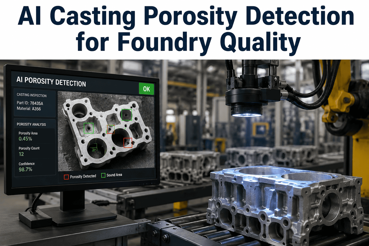
A casting can look flawless on the outside and still fail catastrophically under load because of gas porosity, shrinkage cavities, or inclusions buried inside the metal where no visual inspection could ever find them. X-ray and CT scanning catch these defects but run slowly enough that most foundries only scan a fraction of production, shipping the rest on faith that the process held steady. Book a demo to see AI-assisted porosity detection built for foundry production volumes.
Internal Voids Do Not Show Up Until the Part Has Already Failed
Gas porosity, shrinkage cavities, and inclusions form during solidification and stay invisible from the outside. AI-assisted radiographic and ultrasonic analysis flags them before castings leave the foundry, cutting the volume that gets discovered only after machining, assembly, or field failure.
The Internal Defects Hiding Inside Your Castings
Why Radiograph Review Quality Varies by Shift and Fatigue
Reading radiographs for porosity and inclusions is a skilled task, and it is also a fatiguing one. A technician reviewing hundreds of images per shift experiences measurable accuracy decline over the course of that shift, and the same defect that gets caught at nine in the morning can be missed at nine at night on a busy production day. This is not a reflection of skill, it is a well-documented limit of sustained visual attention on repetitive detail work.
AI-assisted analysis does not replace the technician's judgment on borderline calls, but it does apply a consistent detection threshold to every single image regardless of how many have been reviewed that shift, flagging candidate defects for the technician to confirm rather than requiring them to catch everything cold on every frame.
Stop Shipping Castings on a Sampling Assumption
iFactory applies consistent AI-assisted porosity and inclusion detection across every radiograph reviewed, flagging candidate defects for technician confirmation at foundry production speed.
How Porosity Severity Maps to Casting Risk
| Porosity Class | Typical Void Size | Structural Risk | Common Disposition |
|---|---|---|---|
| Class 1, Fine Scattered | Under 1mm, widely spread | Low for non-critical sections | Accept per spec, log for trend tracking |
| Class 2, Localized Clusters | 1-3mm, grouped | Moderate, depends on load path | Engineering review against section requirements |
| Class 3, Shrinkage Cavity | 3mm or larger, irregular | High in load-bearing sections | Reject or rework, root cause investigation |
| Class 4, Inclusion Cluster | Variable, dense material | High, stress concentration point | Reject, trace back to sand or melt handling |
The classification a foundry uses ultimately depends on the applicable casting specification and the criticality of the section being cast, but the underlying principle holds across standards: severity and location relative to the load path both matter, and a defect acceptable in a non-critical rib can be a mandatory reject in a structural boss.
Connecting Porosity Patterns to Process Parameters
Porosity and shrinkage defects are not random. Gas porosity clustering in specific castings points toward mold moisture or melt degassing issues on a particular heat, while shrinkage concentrated in the same section across multiple castings points toward a gating or riser design that is not feeding that section adequately during solidification.
When defect data is tagged with the heat number, mold, and pour parameters for each casting, patterns that would otherwise look like scattered bad luck become a clear signal pointing at a specific process variable. Foundries that make this connection consistently reduce scrap faster than those treating every rejected casting as an isolated event.
A Six-Point Checklist for Deploying AI-Assisted Porosity Detection
Common Questions About AI Casting Porosity Detection
Does AI-assisted detection replace the radiograph technician's review entirely?
AI-assisted detection is built to support the technician's review rather than replace it, flagging candidate porosity, shrinkage, and inclusion regions for confirmation so the technician's attention is directed to the frames and areas most likely to contain a defect. Final disposition on borderline or ambiguous findings still relies on trained technician judgment, particularly for cases where severity classification depends on context the model was not trained to evaluate. Book a demo to see how detection and technician review work together on your radiographs.
Can the system work with existing X-ray and radiographic equipment already installed in the foundry?
AI-assisted analysis is designed to work with digital radiograph and CT output from standard foundry inspection equipment, so most facilities can integrate detection into an existing imaging workflow without replacing the imaging hardware itself. Film-based systems generally need a digitization step first, since the analysis works on digital image data rather than physical film. Contact support to confirm compatibility with your specific imaging setup.
How does the system distinguish between acceptable microporosity and a rejectable shrinkage cavity?
The model is trained to recognize the distinct visual signatures of each defect type, since gas porosity typically appears as small rounded voids while shrinkage cavities show irregular, jagged boundaries concentrated in thicker sections, and severity classification is aligned to the casting specification your foundry already applies. This allows the flagged output to sort candidates by likely defect type and severity class rather than presenting every anomaly as an undifferentiated flag. Book a demo to review classification accuracy against your specification.
Can defect data be traced back to a specific heat or mold to find the root cause?
When each casting's radiograph is tagged with its heat number, mold identity, and pour parameters at the time of inspection, recurring defect patterns can be traced back to the specific process conditions that produced them, turning scattered rejects into an actionable signal about melt handling, mold moisture, or gating design. This traceability is typically the highest-value output of the system beyond the individual pass or fail decision on each part. Contact support to see root cause trend reporting in action.
What casting materials and processes does AI porosity detection support?
Porosity detection applies across common foundry processes and materials including aluminum sand and die casting, gray and ductile iron, and steel castings, since the underlying defect types, gas porosity, shrinkage, and inclusions, occur across all of these processes even though their typical severity and location differ by alloy and process. Model tuning during setup accounts for the specific radiographic characteristics of your alloy and wall thickness range. Book a demo with sample radiographs from your process for a direct feasibility check.
Catch Internal Casting Defects Before They Leave the Foundry
iFactory applies consistent AI-assisted analysis to every radiograph, ties defect patterns back to heat and mold data, and gives foundry quality teams a repeatable way to close the loop on recurring casting problems.