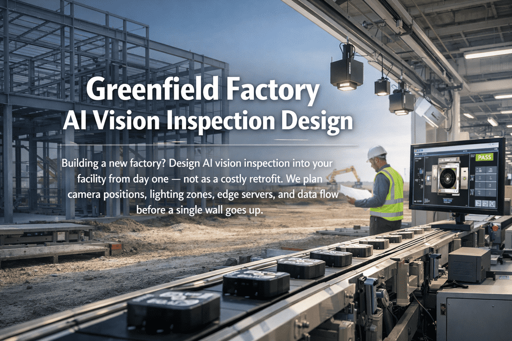
A misplaced camera or wrong lighting angle can drop AI vision accuracy from 99% to 60%. Most AI vision failures aren't algorithm problems — they're optics problems. Shadows from overhead structures, reflections off metal surfaces, vibration from nearby machines, and ambient light contamination destroy the image quality that AI models depend on. Fixing these after construction means tearing open ceilings, re-routing cables, and adding lighting that fights the building's existing geometry. When you engineer camera positions and lighting zones during factory design, every sightline is clear, every light angle is optimized, and every cable run is planned. The result: your inspection system works perfectly from the first production run — with 40% fewer cameras, 95% fewer false positives, and zero blind spots. Get Your Camera Layout Blueprint — we deliver construction-ready camera and lighting specifications before ground is broken.
The Optics Problem: Why Most Vision Projects Fail
Lighting is the single most important factor in machine vision — more important than camera resolution, lens quality, or AI model architecture. It acts as "pre-processing in parallel," affecting every pixel simultaneously during image capture. Physical conditioning of image data through proper lighting is dramatically more efficient than attempting to correct poor contrast through computationally intensive post-processing. Yet lighting is the most commonly neglected element in retrofit installations.
Shadow Interference
Overhead beams, cable trays, and conveyor structures cast shadows that move with sun position throughout the day. AI models trained on shadowless images fail when shadows cross the inspection field. Greenfield fix: specify camera positions in architectural drawings before structural steel is placed.
Specular Reflection (Glare)
Shiny metal, polished plastic, and wet surfaces reflect direct light into the camera sensor, creating hotspots that mask defects. The "illumination W" determines where glare zones fall — and retrofit lighting can't escape them. Greenfield fix: design lighting geometry (angle, diffusion, distance) per surface type during the facility design phase.
Ambient Light Variation
Factory windows, skylights, and overhead fluorescents create lighting that shifts hourly and seasonally. AI accuracy swings 15-30% between morning and afternoon on the same production line. Greenfield fix: design light-isolated inspection enclosures or blackout zones into the factory layout.
Vibration-Induced Blur
Presses, stamping machines, and large conveyors transmit vibration through floors and structures. Even 50μm of camera movement at the wrong moment blurs sub-millimeter defects beyond detection. Greenfield fix: structural isolation and anti-vibration mounts specified in foundation design.
Dealing with lighting or shadow problems on existing vision systems? Get Your Camera Layout Blueprint — we can redesign optics for both retrofit and greenfield scenarios.
Lighting Geometry: 7 Techniques Matched to Defect Types
Every lighting technique reveals different characteristics of the same object. The art of vision system design is matching the right lighting geometry to the specific defect you need to detect — on the specific surface material of your product. Effective illumination acts as physical pre-processing that's dramatically more efficient than software correction.
| Lighting Technique | Geometry | Best For | Surface Type | Defect Types Detected |
|---|---|---|---|---|
| Bright Field (BF) | 45-90° from surface; light reflects toward camera | General surface inspection, dimensional measurement | Flat, matte surfaces | Stains, color variation, print defects, dimensional errors |
| Dark Field (DF) | 0-45° from horizontal; light grazes the surface | Surface texture defects on flat/reflective parts | Polished metal, glass, wafers | Scratches, pits, engravings, edge chips (82%+ detection rate) |
| Diffuse Dome | Hemisphere enclosure; camera through top aperture | Curved, uneven, or highly reflective surfaces | Automotive parts, plastic moldings | Surface defects on curved/textured parts; eliminates hotspots |
| Coaxial (DOAL) | On-axis through beamsplitter; light parallel to lens axis | Mirror-like flat surfaces | Wafers, polished metal, CDs, flat glass | Fine scratches, contamination on specular surfaces |
| Backlight | Light behind object; camera faces light source | Silhouette, dimensional, hole inspection | Any opaque material | Edge profile, hole presence, dimensional measurement (most robust) |
| Structured Light | Laser line at angle to camera; triangulation | 3D profiling, height measurement | Any surface (works on dark/textured) | Weld bead height, solder joint, surface warp, gap measurement |
| Multispectral | Multiple wavelengths (UV, blue, red, NIR) sequenced or filtered | Material composition, hidden features | Food, pharmaceuticals, sorted materials | Contamination, coating thickness, subsurface defects, sorting |
Camera FOV & Resolution Calculation
Correct camera specification starts with the smallest defect you need to detect. The rule of thumb: you need at least 3-5 pixels across the smallest feature of interest for reliable AI detection. From there, the math determines sensor resolution, lens focal length, and working distance.
For a 0.1mm scratch: need 0.02-0.033mm per pixel resolution
50mm FOV at 0.025mm/pixel = 2,000 pixels. For 2D: 2MP minimum. Add 2x safety margin → 5MP recommended.
7.1mm sensor, 300mm WD, 50mm FOV → f = 42.6mm. Select nearest standard: 50mm lens.
For 3D objects, specify minimum DoF that covers product height variation. Trade off with lighting intensity.
Surface Material to Lighting Match
| Surface Material | Challenge | Recommended Lighting | Camera Angle | Special Considerations |
|---|---|---|---|---|
| Polished Metal | Intense specular reflection; glare masks defects | Diffuse dome or coaxial (DOAL) | Perpendicular with DOAL; dome eliminates angle dependence | Polarization filters reduce residual glare by 60-80% |
| Matte/Painted Surfaces | Low contrast between surface and defects | Bright field or dark field depending on defect type | Slight off-perpendicular (5-10°) to avoid direct reflection | Blue light improves fine detail; wavelength selection critical |
| Transparent/Glass | Light passes through; defects nearly invisible | Dark field with low-angle grazing light | Perpendicular camera; lights at 10-20° from surface | Cracks and chips scatter light → bright on dark background |
| Black Rubber/Plastic | Absorbs most light; very low contrast | Backlight for profile; bright field with high intensity for surface | Backlight: camera faces light. BF: perpendicular with boosted LED power | NIR wavelength can penetrate dark surfaces for subsurface defects |
| Textured/Rough Surfaces | Normal texture confused with defects | Structured light for 3D; dome for 2D to flatten texture | 3D: triangulation angle 25-35°. Dome: perpendicular | AI training must include texture variability samples |
| Wet/Oily Parts | Liquid film creates unpredictable specular reflection | Diffuse dome + polarization filter | Perpendicular through dome aperture | Cross-polarization eliminates surface reflection from liquid film |
Struggling with specular reflection or inconsistent lighting on your product? Get Your Camera Layout Blueprint — we'll specify the exact lighting geometry and camera angle for your surface material and defect types.
Anti-Vibration Mounting & Environmental Design
Structural Isolation
Camera supports mounted on separate foundations from heavy machinery. In greenfield design, this is specified in structural drawings — isolation joints between camera gantry pads and press/stamping foundations. Eliminates vibration at the source rather than dampening it.
Anti-Vibration Mounts
Wire rope isolators or elastomeric mounts rated for the frequency range of adjacent equipment (typically 10-200 Hz for presses). Mount natural frequency designed to be 3-5x below the excitation frequency. Validated during construction with vibration survey before camera installation.
Strobe Synchronization
For moving products, high-intensity LED strobing (1-50 μs pulse) freezes motion and eliminates continuous vibration blur. Strobe timing synchronized to encoder signal from conveyor or trigger sensor. Requires camera with global shutter sensor — rolling shutter creates banding artifacts with strobe.
Thermal Management
Camera sensors drift with temperature — hot environments shift pixel response. Cameras near furnaces, ovens, or high-temperature process areas need air-cooled or water-cooled housings. In greenfield, cooling supply (compressed air or chilled water) is designed into the utility routing from the start.
Cabling & Interface Specification
| Interface | Bandwidth | Max Cable Length | Best For | Greenfield Cable Routing |
|---|---|---|---|---|
| GigE Vision | 1 Gbps | 100m (copper CAT6A) | Standard area scan up to 5 MP @ 30 fps | CAT6A shielded in dedicated vision conduit; separate from OT network |
| 10 GigE | 10 Gbps | 100m (OM3/OM4 fiber) | High-res area scan (12+ MP) and moderate line scan | OM4 multimode fiber; star topology from each station to server room |
| CoaXPress (CXP-12) | 12.5 Gbps per lane (×4 = 50 Gbps) | 40m (coax) | Ultra-high-speed line scan (16K @ 100+ kHz) | Dedicated coax runs; frame grabber cards in server room |
| Camera Link HS | Up to 51.2 Gbps | 15-50m (fiber) | Extreme data rate applications; semiconductor inspection | Point-to-point fiber; requires specialized frame grabbers |
| USB3 Vision | 5 Gbps | 5m (direct); 50m (active/fiber extender) | Benchtop/lab inspection; limited factory use | Not recommended for production floor; use GigE or 10GigE instead |
Key Benefits & ROI
Lighting Is 80% of Vision — Get It Right on Paper
iFactory engineers camera positions, lens specifications, and structured lighting zones for your new factory — delivered as construction-ready blueprints that architects and contractors can build from directly.
Frequently Asked Questions
Wrong Lighting Angle = Wrong Results — Every Time
Camera placement and lighting geometry determine 80% of your AI vision success. Design them into your factory blueprints — not as afterthoughts that cost 3-5x more to fix.