Your AI vision cameras generate terabytes daily. A single 12 MP camera at 60 fps produces 5.7 Gbps of raw image data. Multiply that across 10, 50, or 200 inspection stations and you need an infrastructure that can ingest, process, and respond in under 50 milliseconds — not the 200ms+ round-trip a cloud connection requires. Edge AI solves this, but only with correctly planned server rooms, precision cooling, dual-feed power, and dedicated network backbone. Most factories undersize GPU compute by 40-60% because they calculate for average load rather than peak burst, or they provision servers without adequate cooling and watch GPUs throttle to 60% capacity in the first summer. We size GPU servers, design cooling, and plan power and network topology before construction begins — so your vision system runs at full performance from day one. Size Your Edge Infrastructure — we'll calculate the exact GPU count, rack space, power, and cooling for your factory.
Why Edge — Not Cloud — for Factory Vision
Need to justify edge over cloud for your factory vision project? Size Your Edge Infrastructure — we'll provide a detailed TCO comparison for your specific camera count and throughput requirements.
Vision Workload Sizing: Cameras to GPU TOPS
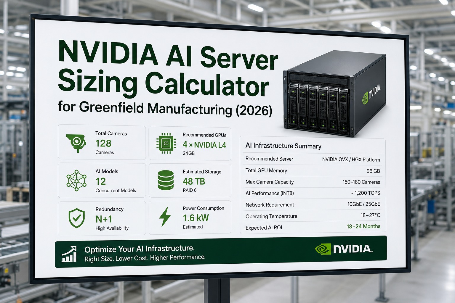
GPU sizing starts with total data throughput — not camera count. A single high-speed line scan camera can demand more compute than ten low-resolution area scan cameras. The formula: cameras × resolution × frame rate × model complexity = required inference TOPS, plus 30% headroom for future expansion and peak burst handling.
| Factory Scale | Camera Config | Total Data Rate | Inference Demand | Recommended GPU | Rack Space |
|---|---|---|---|---|---|
| Small (5-10 stations) | 10× 5 MP area scan @ 30 fps | ~24 Gbps total | ~200-400 TOPS | 2× NVIDIA L40S (or 1× A100) | 2U in single rack |
| Medium (20-50 stations) | 30× area scan + 10× line scan + 5× 3D | ~120 Gbps total | ~1,500-3,000 TOPS | 4× NVIDIA A100 (or 2× H100) | 4-8U, dedicated rack |
| Large (50-100 stations) | 60× area scan + 20× line scan + 10× 3D + 5× hyperspectral | ~350 Gbps total | ~5,000-8,000 TOPS | 4× NVIDIA H100 (or DGX station) | Full rack, N+1 redundancy |
| Enterprise (100-500+ stations) | Multi-line, multi-building deployment | 500+ Gbps total | 10,000+ TOPS | Multiple DGX or HGX pods; distributed architecture | Dedicated server room; multiple racks |
Server Room Physical Design
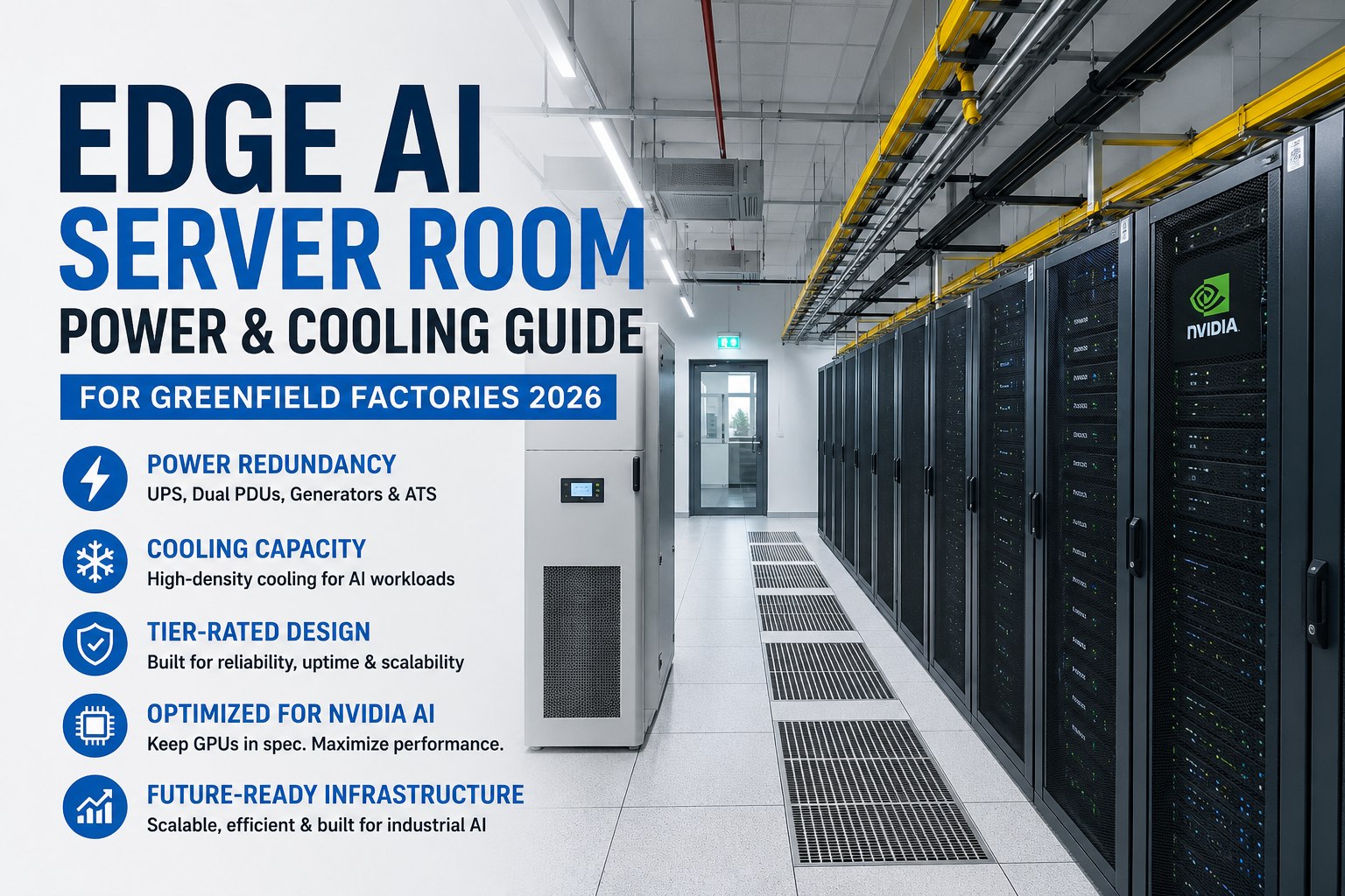
A factory edge server room is not an IT closet. GPU servers generate 2-5x the heat density of standard IT equipment. Without purpose-designed cooling, power, and physical layout, GPUs will thermal-throttle within minutes — dropping from rated performance to 50-60% capacity. In greenfield, the server room is designed as a critical facility room with the same engineering rigor as an electrical switchgear room.
Location: Within 50m of Inspection Points
Fiber latency adds ~5 ns/meter. More critically, longer cable runs increase failure points and installation cost. The server room should be centrally located relative to inspection stations. In greenfield, this is specified in the facility layout during schematic design — not discovered during commissioning.
Raised Floor / Overhead Cable Tray
Under-floor air distribution for front-to-back cooling airflow through server racks. Overhead cable trays for fiber and power — separated to prevent EMI. Floor loading capacity: 1,500-2,000 kg/m² minimum for GPU-dense racks (standard office floor is 250-500 kg/m²).
Fire Suppression
Clean agent (FM-200 or Novec 1230) fire suppression — not water sprinklers. Pre-action detection (VESDA smoke detection) for earliest possible alert. Designed into the room from construction — retrofitting fire suppression around installed equipment is expensive and disruptive.
Physical Security & Access Control
Card/biometric access control. Environmental monitoring (temperature, humidity, water leak detection) with alerts to maintenance and IT teams. CCTV monitoring. Designed as a secure, controlled-access room in the facility security plan.
Precision Cooling & Power Engineering
| Design Parameter | Specification | Why It Matters | Greenfield Advantage |
|---|---|---|---|
| Cooling Capacity | Plan 1.5-2× total GPU TDP; N+1 CRAC/CRAH redundancy | GPUs throttle at 80-85°C junction temperature. Without adequate cooling, rated TOPS drops to 50-60% | HVAC sized for GPU heat load from day one; chilled water piped before walls go up |
| Temperature Range | 20-25°C inlet air; max 27°C (ASHRAE A1) | Every 10°C above optimal reduces GPU lifespan by ~50% (Arrhenius acceleration) | Precision CRAC units specified in MEP design; not retrofitted window AC |
| Airflow | Front-to-back (cold aisle/hot aisle containment) | Prevents hot exhaust recirculating to GPU intake. Mixing hot/cold air wastes 30-40% cooling capacity | Aisle containment designed into rack layout; raised floor plenum sized for airflow |
| Power — Primary | Dual-feed utility power; automatic transfer switch (ATS) | Single-feed power = single point of failure. ATS switches to backup feed in <10 seconds | Dual feeds from different utility transformers; specified in electrical design |
| Power — UPS | Online double-conversion UPS; 15-30 min runtime | Bridges gap between power loss and generator start. Protects against sags, surges, harmonics | UPS room adjacent to server room; battery weight factored into structural design |
| Power — Generator | Diesel generator with auto-start; N+1 if critical | Extended outage protection. Generator fuel supply sized for 24-72 hours | Generator pad, fuel storage, and exhaust routing designed into site plan |
| Power Density | 10-30 kW per rack for GPU servers (vs. 5-8 kW for standard IT) | Undersized PDUs and breakers trip under GPU load; standard racks can't handle the heat | Power distribution designed for GPU density from the start; bus bars, PDUs, breakers all rated |
Not sure what cooling capacity your GPU deployment needs? Size Your Edge Infrastructure — we'll calculate BTU/hr, airflow CFM, power draw, and UPS runtime for your exact GPU configuration.
Network Topology Design
Vision data is the highest-bandwidth traffic on a factory network. A single 12 MP camera at 60 fps generates more data than an entire production floor of PLCs and SCADA nodes. Vision traffic must be isolated from OT and IT networks on a dedicated backbone — otherwise, inspection latency becomes unpredictable and production network performance degrades.
1 GbE or 10 GbE per camera (depending on resolution/fps). PoE+ for camera power where applicable. CAT6A shielded for GigE Vision; OM4 fiber for 10 GbE. Max 100m horizontal run. Dedicated vision VLAN — no shared ports with OT devices.
25-100 GbE uplinks from access switches to aggregation layer. Fiber trunk cables (OM4 multimode or OS2 singlemode for runs >300m). Redundant paths (LAG/MLAG) for zero-downtime failover. Managed switches with QoS for vision traffic prioritization.
100 GbE or 200 GbE into GPU server NICs (ConnectX-7 or equivalent). Low-latency switching (<1 μs port-to-port). Direct fiber connections to server room. This is the bottleneck point — aggregation bandwidth must exceed total camera throughput with 30% headroom.
Separate interface from vision ingress. 1-10 GbE for inspection results, reject gate signals (Ethernet/IP, Profinet), and dashboard data. Firewall/DMZ between vision network and OT/IT networks. Only metadata and decisions cross this boundary — raw images stay on vision network.
Failover & Redundancy Architecture
GPU Failover (N+1)
Provision one additional GPU server beyond minimum required capacity. If any single server fails, workload automatically redistributes to remaining servers. Orchestration software (Kubernetes or custom load balancer) manages camera-to-GPU assignment dynamically. Mean time to failover: <5 seconds.
Network Path Redundancy
Dual fiber paths from every access switch to aggregation layer (LAG/MLAG). If any single fiber or switch fails, traffic fails over to the redundant path with zero packet loss. Spanning Tree or EVPN-VXLAN fabric eliminates loops while maintaining redundancy.
Power Redundancy
Dual-corded servers with A+B power feeds from separate UPS systems. Each UPS sized to carry full server room load independently. Generator auto-starts within 10 seconds of utility loss. UPS bridges the gap. Result: no single power failure stops vision inspection.
Graceful Degradation
If capacity drops below full coverage, AI prioritizes critical inspection stations over non-critical ones. Operator dashboard shows degraded status with estimated time to recovery. No silent failures — every camera and GPU reports health status continuously. CMMS auto-generates maintenance tickets for failed components.
Key Benefits & ROI
Your Cameras Are Only as Good as the Compute Behind Them
iFactory designs complete edge AI infrastructure for factory vision — GPU sizing, server room layout, precision cooling, dual-feed power, fiber backbone, and failover architecture — delivered as construction-ready specifications.
Frequently Asked Questions
Undersized Compute = Missed Defects at Production Speed
GPU thermal throttling, network congestion, and power brownouts don't show up in pilot projects — they show up at full production speed on hot summer days. Design for reality, not for demos.