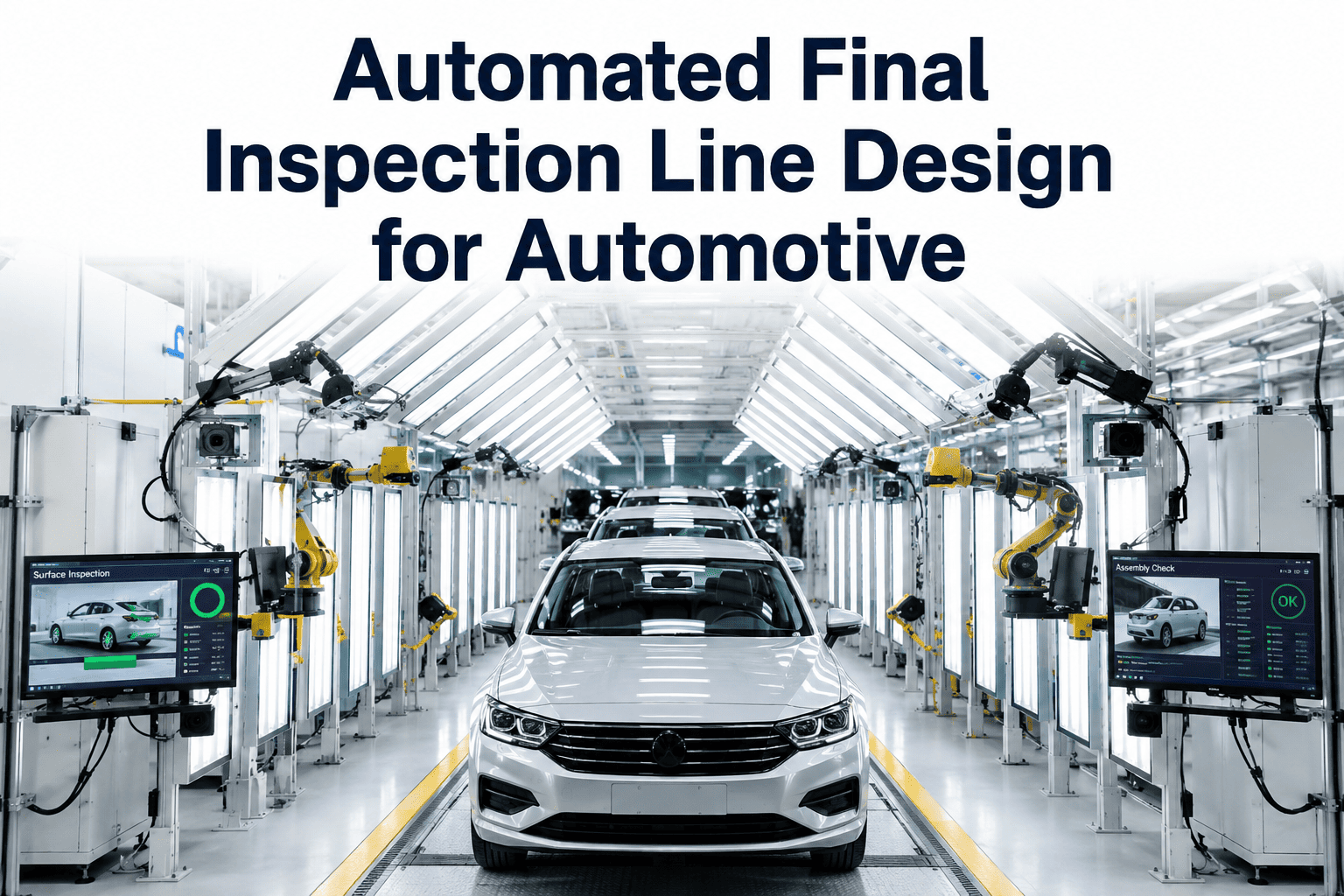
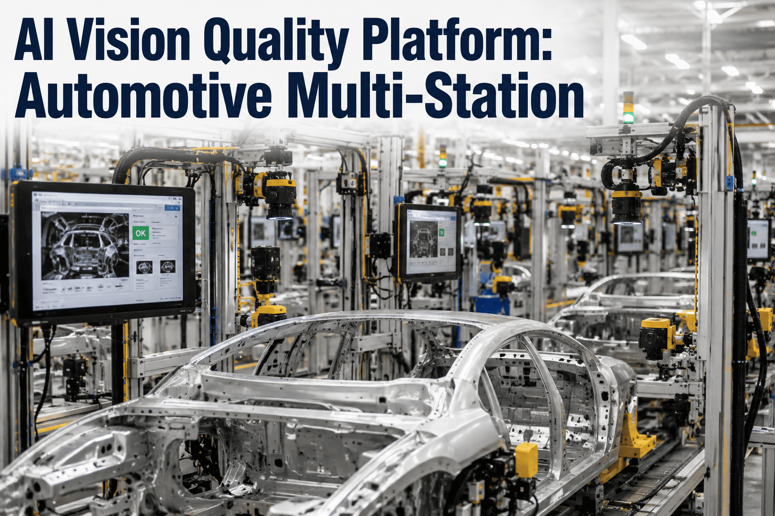
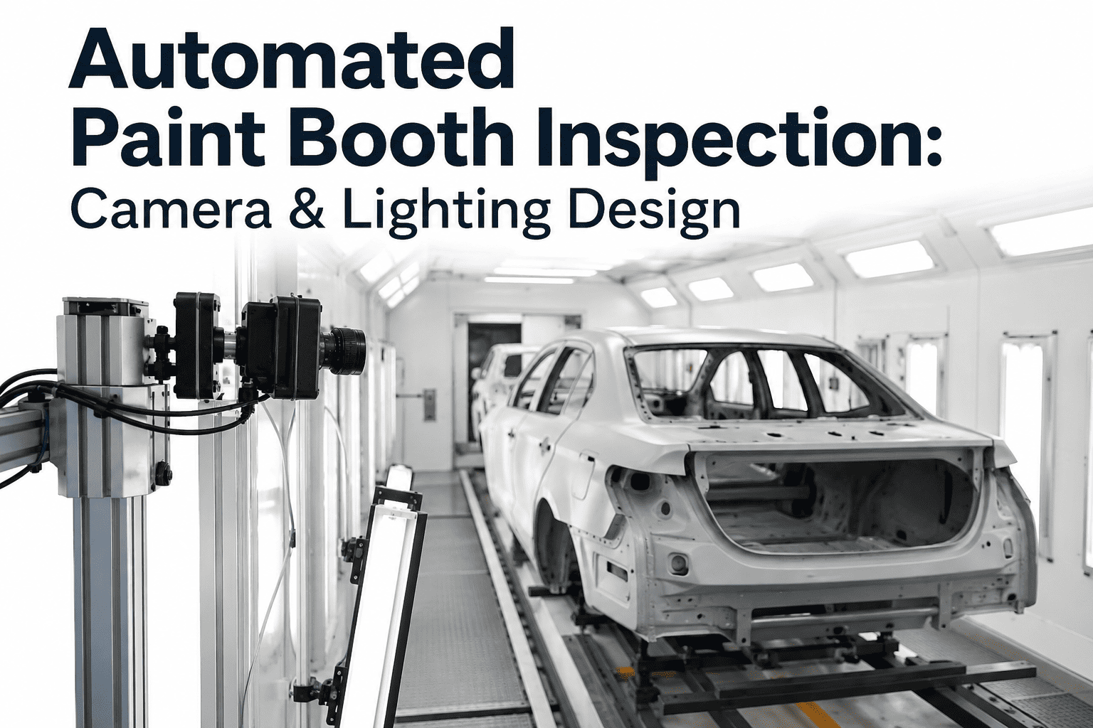
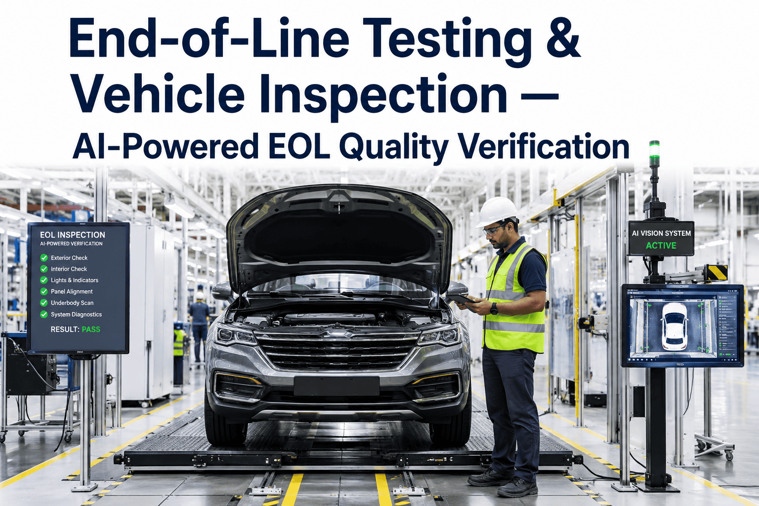
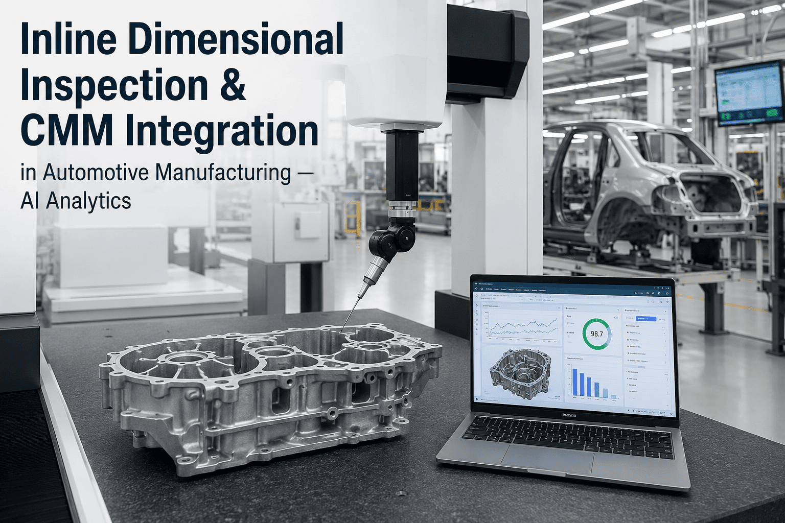
Most automated final inspection lines fail their first six months not because the AI models are weak, but because the physical layout around them was never designed for what those models actually need to see. A camera angled a few degrees wrong, a station spaced too tight for a vehicle to fully settle, or lighting that shifts with the time of day can quietly undermine detection accuracy in ways that look, on paper, like a software problem. The plants getting consistently strong results treat line design as inseparable from the AI itself, planning station layout, camera positioning, and sensor placement together from day one instead of bolting inspection onto an existing conveyor after the fact. Getting this right the first time avoids months of retrofitting later. iFactory's inspection line design team works through this layout planning before a single camera goes on the wall.
Final Inspection Line Design
Designing an Automated Final Inspection Line That Actually Works
Station layout, camera positioning, and sensor integration decide detection accuracy long before any AI model runs. See how to plan a line that gives the system a fair chance to succeed.
Why Layout Decisions Made First Determine Accuracy Later
An inspection AI model can only be as good as the image or sensor data it receives, and that data quality is set almost entirely by physical design choices made before the software is ever configured. Retrofitting camera position or lighting after a line is running means re-collecting training data, re-validating thresholds, and often re-certifying the entire station, which is a far more expensive path than planning it correctly the first time.
1
Approach Zone
Vehicle settles and stabilizes before entering the capture zone
2
Exterior Capture
Multi-angle cameras cover body panels, gaps, and paint surface
3
Interior/Underbody
Fixed and articulating sensors cover cabin and chassis details
4
Decision Zone
Results aggregated per VIN, pass/hold/reject determined
The Physical Variables That Make or Break Detection
Camera Angle and Distance
A few degrees of angle change or an inconsistent working distance can shift how a defect appears enough to confuse a trained model.
Lighting Consistency
Ambient light bleeding into the capture zone from doors, skylights, or shift changes introduces variation the model was never trained on.
Vehicle Positioning Tolerance
Line speed variation or conveyor drift changes where the vehicle sits relative to fixed cameras, shifting the frame each time.
Station Spacing
Too little distance between stations doesn't give sensors time to complete a full capture cycle before the next vehicle arrives.
Planning Camera and Sensor Coverage by Zone
A full-vehicle inspection line typically needs distinct sensor strategies for different zones of the vehicle, since exterior paint and gap inspection, interior fit and finish, and underbody or chassis checks all have different lighting, angle, and resolution requirements. Planning these zones separately, rather than assuming one camera configuration fits every surface, is what keeps detection accuracy consistent across the whole vehicle.
| Inspection Zone | Primary Sensor Type | Key Layout Requirement |
|---|
| Exterior body and paint | High-resolution multi-angle cameras | Controlled, consistent overhead lighting |
| Panel gaps and flush | Structured light / 3D profiling | Fixed working distance, minimal vibration |
| Interior cabin | Articulating or handheld-style cameras | Access clearance for door and trunk openings |
| Underbody / chassis | Fixed under-line camera arrays | Adequate ground clearance and pit design |
Want a second opinion on your planned camera and sensor layout before installation? Talk to our team about a design review.
From Layout Plan to Commissioned Line
1
Map Defect Types
Identify every defect category the line needs to catch and where on the vehicle it typically occurs
2
Design Zones
Assign sensor types, angles, and lighting per vehicle zone based on defect requirements
3
Simulate and Test
Validate coverage and image quality with real vehicles before full production commitment
4
Commission and Tune
Fine-tune thresholds against live production data once the line is running
What a Well-Designed Line Delivers
Consistent
Image quality across shifts, seasons, and line speed variation
Full
Coverage across exterior, interior, and underbody zones
Fewer
Retrofit cycles caused by layout issues discovered after go-live
Who Should Be at the Table During Layout Design
01
Quality Engineering
Defines which defect types and severity levels the line must reliably catch before layout decisions get made.
02
Plant Facilities
Manages lighting, conveyor speed, and pit or clearance constraints that shape what layouts are physically possible.
03
Vision System Integrators
Translate defect and coverage requirements into specific camera, lighting, and sensor specifications.
04
Line Operators
Provide practical input on vehicle positioning tolerance and how line speed actually behaves day to day.
Common Layout Mistakes to Avoid
Designing for the Software First
Choosing an AI vendor before the physical layout is planned often forces compromises the vendor's model wasn't built for.
Uniform Lighting Assumptions
Assuming one lighting setup works for every vehicle color and surface finish ignores how reflectivity varies significantly.
No Buffer for Line Speed Changes
Layouts designed for a single fixed line speed struggle when production ramps or throughput targets change.
Skipping the Simulation Phase
Going straight from design to full installation without testing coverage on real vehicles first invites costly rework.
Frequently Asked Questions
How long does it typically take to design and commission a final inspection line?
Timelines vary with the number of defect types and vehicle zones covered, but a thorough design phase including simulation and testing generally takes several weeks before installation begins, followed by a tuning period once the line is running against live production. Rushing the design phase to hit an installation date is one of the most common causes of post-launch rework.
Our team can help scope a realistic timeline for your specific line.
Can an existing conveyor line be retrofitted with inspection stations?
Yes, though retrofits require careful assessment of existing line speed, spacing, and lighting conditions, since these were likely never designed with vision system requirements in mind. A retrofit project typically needs more design iteration than a greenfield line built with inspection in mind from the start.
How much does vehicle positioning variation actually affect accuracy?
It can matter significantly, since even a few centimeters of positional drift changes the frame a fixed camera captures, which is why many layouts include guided approach zones or dynamic camera tracking to compensate. Testing positioning tolerance during simulation is one of the most valuable steps before committing to a final layout.
Does every vehicle zone need the same camera resolution?
No, resolution and sensor type should match the defect scale each zone needs to catch — fine paint defects need higher resolution and controlled lighting than broader fit-and-finish checks, so a uniform camera specification across the whole line usually wastes budget in some zones while underperforming in others.
Where should a plant start when planning a new inspection line?
Start with a complete map of the defect types the line needs to catch and where on the vehicle they typically occur, since that map drives every downstream decision about camera type, angle, and lighting for each zone.
Book a demo to see how that mapping process typically runs.
A Line Designed Right the First Time Saves Months of Rework.
Plan Your Final Inspection Line Layout Before You Build It
Bring your defect list and current line constraints. We'll help you design camera, sensor, and station layout that gives your inspection AI the best chance to succeed.