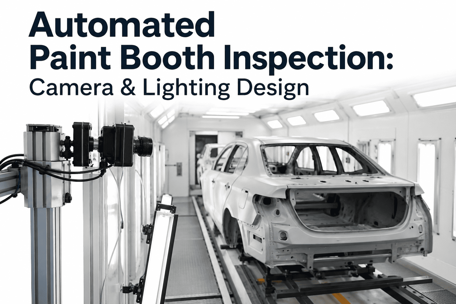
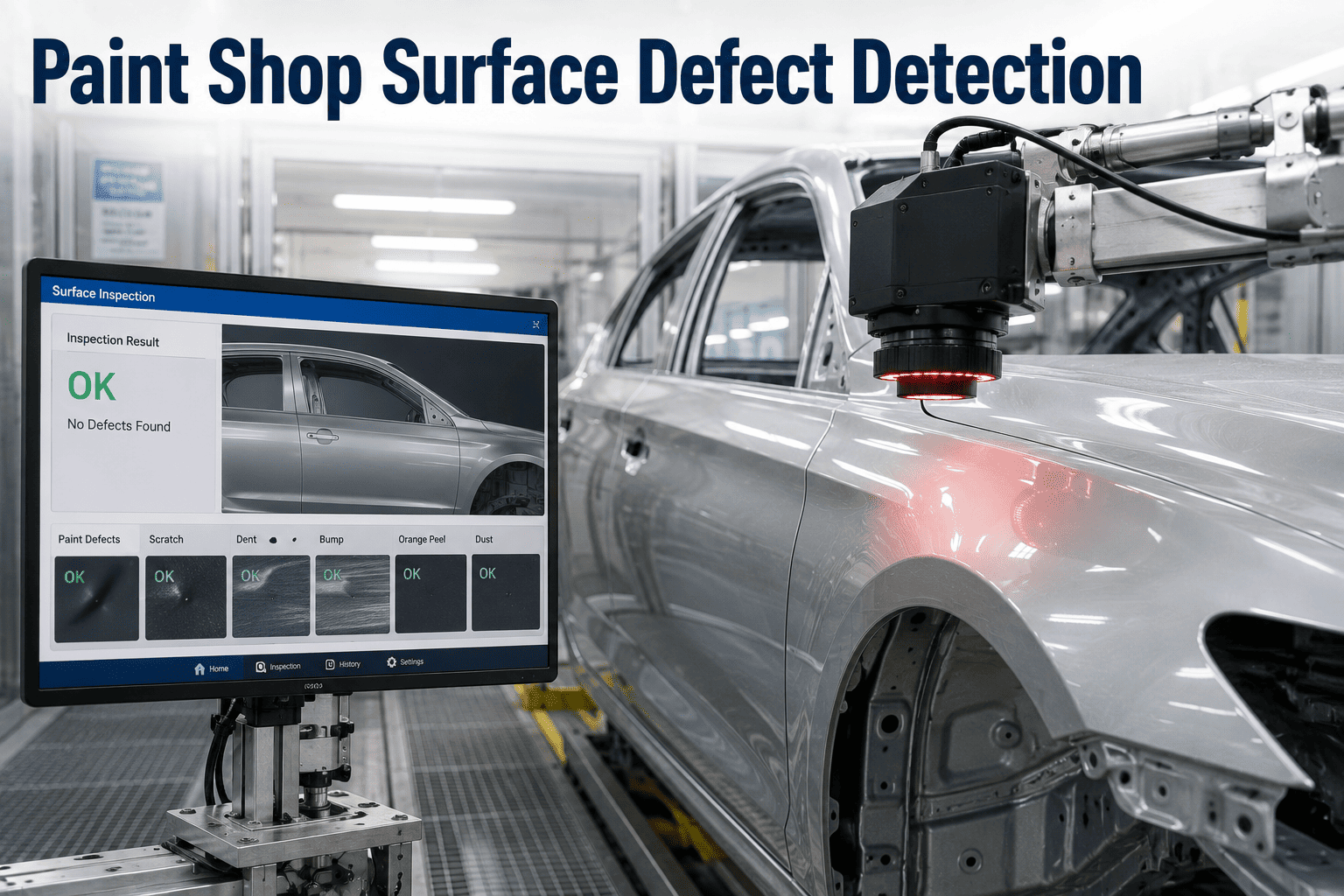
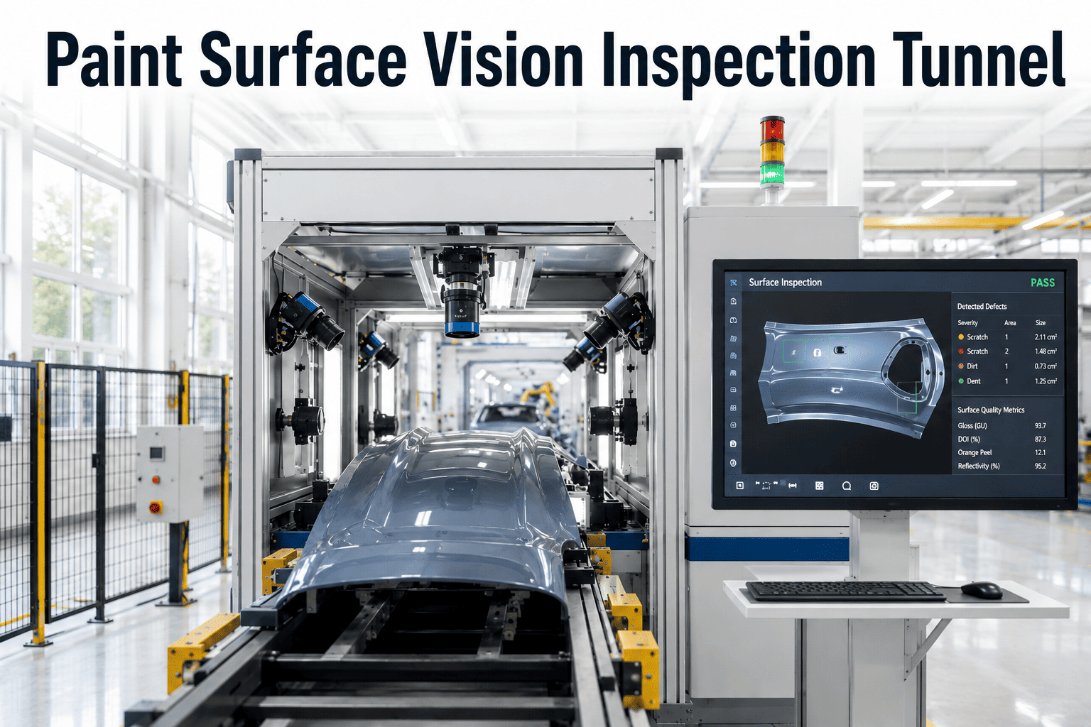
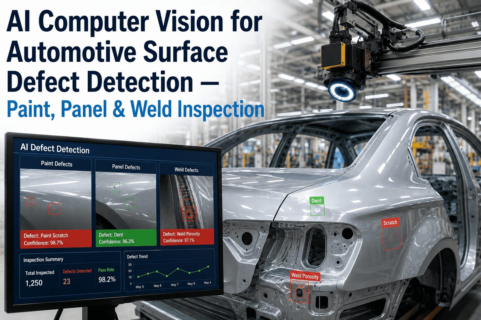
The camera and lighting configuration around a paint booth determines what an AI inspection system can and cannot see, and this decision matters more than which vision model gets deployed on top of it. A camera aimed straight at a panel under flat, even lighting will miss orange peel texture and shallow craters almost entirely, because these defects only reveal themselves when light rakes across the surface at an angle. Getting this wrong means retraining models against footage that never contained the defect signature in the first place, no matter how sophisticated the algorithm. Plants planning a new inspection deployment or retrofitting an existing booth need to think about camera geometry and illumination technique before a single line of model training begins, and our support team can walk through the specifics of your booth layout.
Vision Hardware · Paint Booth Design
Camera and Lighting Design for Automated Paint Booth Inspection
Structured illumination and multi-angle camera placement determine whether an AI system can actually see the defects it is meant to catch — here is how to design that setup correctly.
Illumination Techniques
Four Lighting Approaches, Each Revealing a Different Defect Class
No single lighting angle catches every defect type. A well-designed booth inspection zone layers several techniques so nothing depends on one camera catching one lucky reflection.
01
Structured Light Projection
A grid or stripe pattern is projected onto the painted surface, and distortion in the reflected pattern reveals texture variation like orange peel and low-lying craters that flat lighting would smooth over completely.
02
Deflectometry
A known pattern is reflected off the glossy surface and the distortion pattern is mathematically reconstructed into a surface map, making this one of the most sensitive methods for detecting subtle waviness across an entire body panel.
03
Darkfield Illumination
Light is angled so that it only reflects into the camera when it strikes a surface irregularity, which makes fine scratches and dust nibs stand out sharply against an otherwise dark background.
04
Raking Light
Light directed at a shallow angle across the panel surface casts long shadows from even minor surface deviations, a technique long used by human inspectors that AI cameras replicate at fixed, repeatable angles.
Camera Placement
Where Cameras Go and Why It Changes Detection Rate
A single fixed camera position, no matter how good the sensor, will always leave part of a curved body panel underexposed or angled wrong for defect visibility. Full coverage requires thinking in zones.
Overhead Zone
Cameras mounted above the conveyor path capture the roof, hood, and trunk lid — horizontal panels where dust settling and orange peel are most likely to accumulate during cure.
Side Elevation Zone
Angled side-mounted cameras cover doors, fenders, and quarter panels, typically paired with raking light to catch the vertical-surface runs and sags gravity tends to produce.
Low-Angle Zone
Cameras positioned near floor level catch rocker panels and lower body sections that overhead and side cameras cannot reach without a blind spot.
Rotating Multi-Angle Rig
Some booths use a robotic arm-mounted camera that circles the body during a brief dwell, adding coverage flexibility for complex curvature without adding fixed camera count.
Every Booth Layout Is Different — We Design Around Yours
iFactory's deployment team maps camera and lighting placement against your specific booth geometry, conveyor speed, and panel mix before any model training starts.
Hardware Specification
Comparing Camera and Lighting Configurations
Configuration
Best For
Limitation
Single fixed overhead camera
Low-cost pilot on horizontal panels only
Misses vertical panel defects entirely
Multi-camera fixed array
Full-body coverage at consistent throughput
Higher upfront hardware and mounting cost
Deflectometry rig
Subtle waviness and clearcoat film variation
Requires stable, vibration-free mounting
Darkfield plus raking combo
Fine scratches and dust nibs on any panel angle
Needs precise angle calibration per panel type
Robotic multi-angle rig
Complex curvature and low fixed-camera budgets
Slower cycle time than fixed-array setups
Design Checklist
Six Questions to Answer Before Installing Camera Hardware
1
What is the conveyor dwell time available for image capture at each zone, and does it match camera exposure needs?
2
Which panel geometries in the current vehicle mix require dedicated low-angle or high-curvature coverage?
3
What ambient light sources near the booth exit could interfere with structured lighting or darkfield setups?
4
Is the mounting structure stable enough for deflectometry, which is sensitive to vibration and drift?
5
How will metallic and pearl finishes in the color mix affect camera exposure settings across zones?
6
What is the plan for periodic camera and lighting calibration as booth conditions shift over time?
Frequently Asked Questions
Camera and Lighting Design — Common Questions
Do we need to replace our existing camera hardware to add AI inspection?
Not always. If existing cameras meet resolution and frame rate requirements for your conveyor speed, they can often be integrated with new lighting and a vision model layered on top. The more common upgrade is adding structured or raking lighting fixtures rather than replacing every camera, since lighting technique affects defect visibility more than raw camera resolution in most orange peel and texture use cases.
Contact support for an assessment of your current hardware.
How many cameras does a typical booth exit inspection zone need?
This depends heavily on body size and panel complexity, but most full-coverage deployments use somewhere between twelve and twenty-four cameras positioned across overhead, side, and low-angle zones to eliminate blind spots. Fewer cameras can work for a narrower pilot scope focused on one or two panel types, with expansion planned as the system proves value on the initial zone.
Why does deflectometry need such a stable mounting structure?
Deflectometry works by measuring how a known reflected pattern distorts across the panel surface, and even small vibrations or drift in the projector or camera position introduce noise that gets mistaken for surface waviness. Mounting on isolated, rigid structures away from conveyor motors and compressed air lines is standard practice to keep the measurement stable enough to trust.
Can one lighting setup cover both metallic and solid color finishes?
Generally no, at least not with identical settings. Metallic and pearl finishes scatter light differently because of flake orientation, so exposure and lighting angle calibration typically need separate profiles per finish type, switched automatically based on the vehicle's paint code as it approaches the inspection zone.
Book a demo to see how profile switching works in practice.
How often does the camera and lighting system need recalibration?
Most deployments run a calibration check on a defined interval, often weekly, plus an automatic check whenever a known reference panel is passed through the zone. Calibration drift is usually gradual, caused by dust accumulation on lenses or small mounting shifts over time, and catching it early through scheduled checks prevents a slow decline in detection accuracy that would otherwise go unnoticed for weeks.
Get the Camera and Lighting Design Right the First Time
iFactory's team maps illumination technique and camera placement against your booth geometry before training begins, so the vision model is working with footage that actually shows the defects you need to catch.