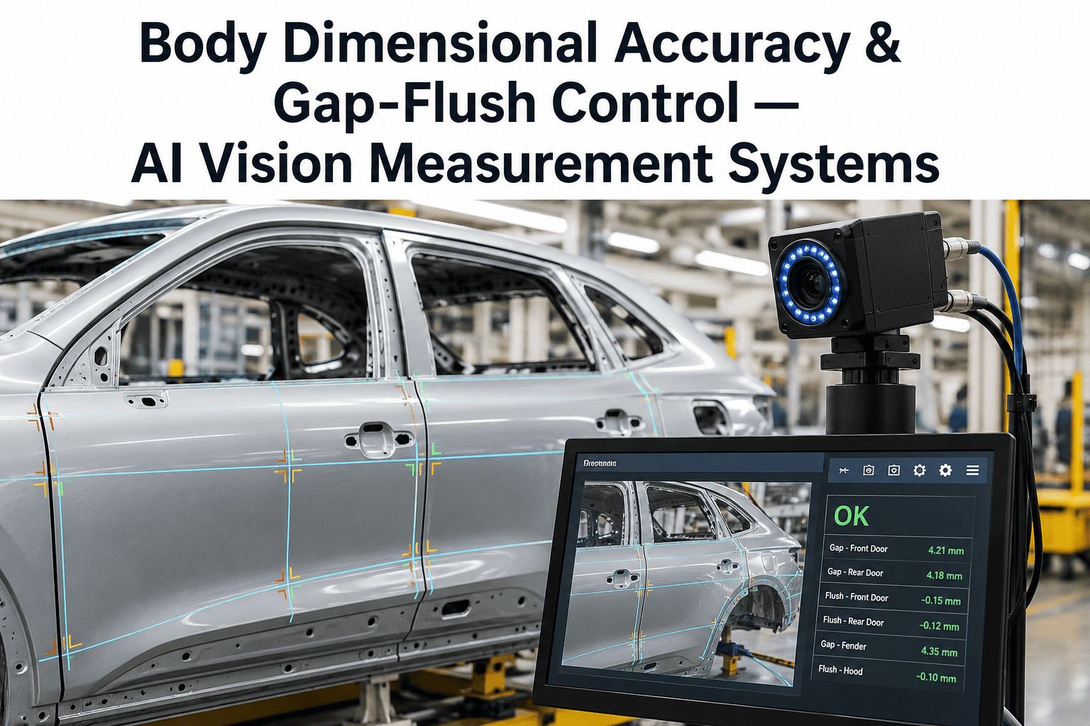
Every vehicle that rolls off a modern assembly line carries roughly 150 individual panel-to-panel junctions where doors, hoods, fenders, and trunk lids meet — and each one has its own gap and flush tolerance that must be held to within a few tenths of a millimeter. Get it wrong and the consequences are not cosmetic footnotes. Wide door gaps let in wind noise at highway speed, uneven hood-to-fender flush throws off aerodynamic drag figures, and a fender sitting proud of its neighbor by more than a millimeter is often the single detail that convinces a walk-around buyer the car "doesn't feel finished," even when they can't articulate why. Body shops have relied on periodic CMM sampling and handheld feeler gauges for decades, checking a handful of vehicles per shift while thousands roll past unmeasured. AI vision measurement systems close that gap by checking dimensional accuracy on every body, at every station, continuously — and the plants making that shift are the ones catching drift before it reaches a customer's driveway. Compare how continuous measurement changes your quality curve with a Book a Demo.
Sub-Millimeter Body Accuracy Isn't a CMM Sampling Problem Anymore
AI-powered gap and flush measurement checks structural geometry and panel alignment on 100% of bodies at line speed — not a sampled few per shift — catching dimensional drift at its source before it becomes a customer-facing fit-and-finish complaint.
What "Gap" and "Flush" Actually Measure — and Why Both Are Needed
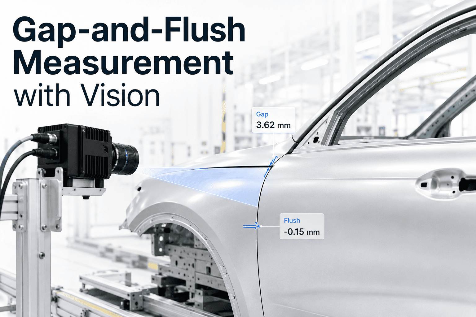
Gap and flush are two different measurements of the same panel junction, and a station can pass one while failing the other. Gap describes the distance between two adjacent components — the space between a door edge and the fender it sits beside. Flush describes whether those two surfaces sit on the same plane once installed — whether the door skin and the quarter panel line up level with each other, or whether one sits proud or recessed relative to its neighbor. A door can have a perfectly specified 4mm gap on all sides and still fail inspection if it's sitting 1.5mm higher than the fender it meets, because that flush deviation is what a customer's eye and fingertip actually notice during a showroom walk-around.
Gap
The linear distance between two adjacent panel edges, measured perpendicular to the seam. Controls wind noise, water ingress paths, and visual seam consistency across the body.
Flush
The height difference between two adjacent surfaces at their shared edge, measured normal to the panel plane. Controls aerodynamic drag, perceived quality, and closing effort consistency.
Where Gap and Flush Checks Happen Across the Body
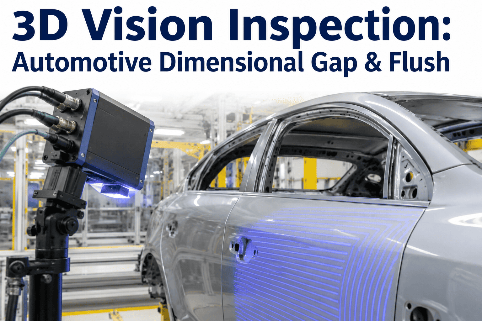
A complete inspection pass covers dozens of measurement points spanning every closure panel, because each panel-to-panel junction carries its own engineering tolerance derived from the vehicle's 3D CAD model rather than a generic industry default. Vision-based systems capture every point in a single pass as the body moves through the station, which is what makes full coverage practical at production line speed instead of requiring an operator to visit each location individually with a handheld gauge.
Upper, lower, and B-pillar edges checked against fender and rocker panel — the highest-visibility gap zone on the vehicle.
Front-of-vehicle flush line that most directly affects both aerodynamic performance and first-impression fit quality.
Rear closure alignment against quarter panels, checked for both static gap and dynamic closing behavior.
Smaller closures that are frequently under-measured manually but still contribute to overall perceived fit quality.
See Every Panel Junction Measured on Every Body
iFactory's vision measurement stations run at final assembly line speed, comparing every body against its CAD-defined tolerance and routing out-of-spec vehicles to adjustment before they reach the next station.
Why Periodic Manual Checks Miss Drift Between Samples
Traditional dimensional quality control relies on a coordinate measuring machine checking a small number of bodies per shift, supplemented by feeler-gauge spot checks on the line. Both methods are accurate when performed, but neither is continuous. Tooling wear, fixture drift, and robot calibration shift gradually over thousands of cycles, and a sampling plan built around checking one body in fifty or one hundred can easily run for hours after a process has started drifting out of tolerance before the next sample catches it. By the time the CMM flags a problem, dozens or hundreds of vehicles carrying the same defect may already be downstream, some already painted, trimmed, or shipped.
| Dimension | CMM Sampling | Feeler Gauge Spot Check | AI Vision Inline |
|---|---|---|---|
| Coverage per shift | A handful of bodies | Operator-dependent, few points | Every body, every point |
| Measurement points per body | Full but slow | Limited to reachable zones | Dozens of points in seconds |
| Time to detect drift | Hours between samples | Inconsistent | Next body through the station |
| Traceability by VIN | Partial | Rarely recorded | Full measurement record |
Finding Where a Dimensional Deviation Actually Started
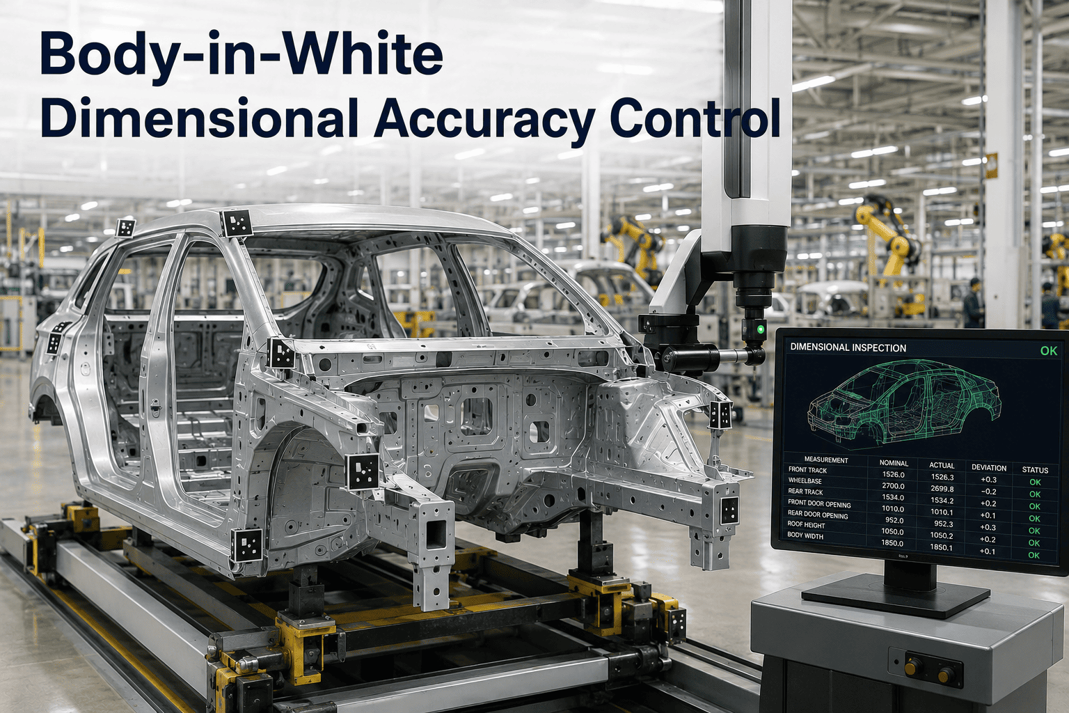
A gap or flush deviation at final assembly rarely originates at final assembly. The root cause usually sits upstream — in the stamping die, the weld fixture, or the marriage station where body-side and underbody are joined — and tracing it backward requires comparing measurements taken at multiple stages of the build, not just the final check. Quality teams that measure at both the body shop and final assembly can compare the two data sets directly to isolate exactly where a deviation was introduced, rather than guessing at which of a dozen upstream processes is responsible.
Stamped panel measured at press exit for die wear and material spring-back variation.
Body-in-white measured post-weld for fixture drift and weld sequence deviation.
Marriage station measured where body and underbody are joined and stack-up tolerances compound.
Final assembly measured for closure panel fit before the vehicle leaves the plant.
Comparing readings across all four stages by VIN turns a reactive adjustment station into a predictive maintenance signal for the upstream tooling and fixtures actually causing the drift.
We were catching maybe one gap issue in twenty on the CMM sample plan, and the other nineteen were reaching final inspection or, worse, the customer. After putting vision measurement at every closure station, we found a hood hinge fixture that had been drifting for weeks — nobody knew because the sample plan kept missing it. That single fixture fix cut our end-of-line dimensional rework by more than a third.
Frequently Asked Questions
Q: How does the system know what the correct gap and flush values are for our specific vehicle?
Measurement targets are pulled directly from your vehicle's 3D CAD model, and real-world camera data is compared against that model at each defined measurement section to calculate the actual deviation. That means acceptance criteria are specific to your body design and engineering tolerances rather than a generic industry default, and they can be updated as tolerances change across model years or trim variants without re-engineering the inspection station. Talk to Support about mapping your CAD data into a measurement program.
Q: Will adding vision measurement stations slow down our final assembly line?
Vision-based gap and flush stations are built to run inline at the pace of final assembly, capturing measurements as the vehicle passes through rather than requiring a dedicated dwell station where the line stops. Camera placement and calibration are planned around your specific line layout and vehicle geometry during setup, so the measurement pass adds no meaningful cycle time to the station it occupies.
Q: Should we measure at the body shop, final assembly, or both?
Many quality teams measure at both stages because data collected early in the body shop can be directly compared against final assembly readings to isolate exactly where a deviation was introduced. Measuring only at final assembly tells you a vehicle failed, while measuring at both stages tells you which upstream process caused the failure — the difference between reactive rework and a fixable root cause.
Q: What happens when a vehicle fails a gap or flush check on the line?
The system flags the VIN and routes the vehicle to an adjustment station rather than allowing it to continue toward paint or trim with an unresolved dimensional issue. A technician makes the correction — commonly a hinge or striker adjustment — and the vehicle is re-measured on the spot to confirm it now meets specification before release to the next station. See how routing and re-measurement work in a live line layout by scheduling a Book a Demo.
Q: How does this data integrate with our existing quality management system?
Every measurement is timestamped and tied to the vehicle's VIN, generating a permanent dimensional record that feeds into IATF 16949 quality documentation, PPAP packages, and customer-specific reporting requirements without manual data entry. Historical measurement trends across stations also become the input for identifying tooling and fixture wear before it produces an out-of-tolerance body, turning inspection data into a maintenance signal rather than a pass/fail log.
Stop Finding Dimensional Drift After It's Shipped
Move from sampled CMM checks to continuous, VIN-traceable gap and flush measurement across every closure point on every body.