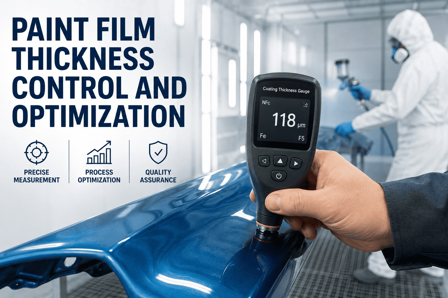
A hood panel running twelve microns thinner than spec doesn't look any different on the line — it passes visual inspection, it feels the same under a gloss meter's quick check, and it ships. Two years later that panel is the one showing early stone-chip corrosion while every other panel on the same vehicle holds up fine, and nobody can trace it back to a single spray pass because nobody was measuring film thickness in real time when it happened. Dry film thickness is the one paint quality variable that is both completely invisible and completely decisive, which is exactly why the plants who inline-gauge it are catching material waste and warranty exposure that everyone else discovers only after the fact. If your DFT data still comes from spot checks with a handheld probe, book a session with an iFactory paint quality engineer to see what continuous inline gauging looks like across a full body.
iFactory Paint Shop Intelligence
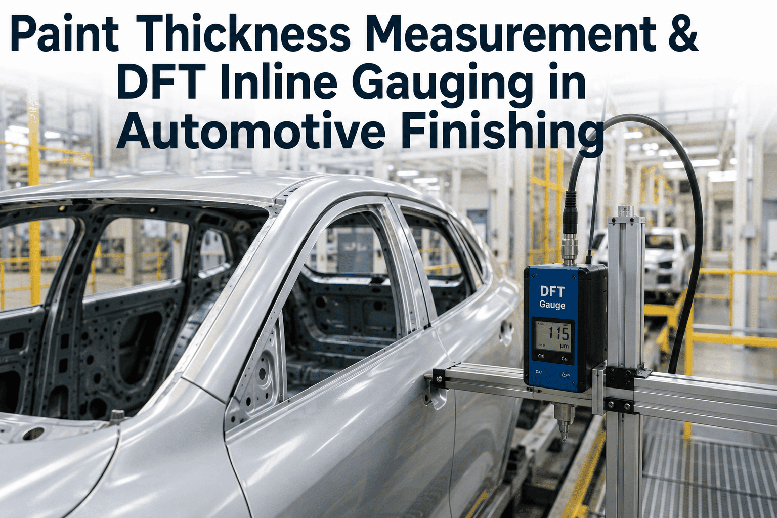
Paint Thickness Measurement & DFT Inline Gauging in Automotive Finishing
Film thickness decides corrosion life, chip resistance, and material cost simultaneously — and it varies more across a single body than most quality programs ever check. This guide covers what inline DFT gauging actually measures, how AI correlates it back to spray parameters, and what changes when thickness data flows continuously instead of arriving as a spot sample.
8-15%
Typical paint material savings from thickness optimization
±5µm
Typical variance target for well-controlled inline gauging
100%
Of body panels measured versus a handful of spot samples
6 wk
Typical time to first validated thickness-to-spray correlation
Why Spot Sampling Was Never Enough
Traditional dry film thickness verification relies on a technician walking a handful of panels per shift with a handheld eddy current or magnetic induction probe, recording readings at a handful of fixed points, and flagging anything outside a broad tolerance band. This tells you whether the average body is roughly in range. It tells you almost nothing about the variation within a single body — a hood that runs thick while a rocker panel runs thin, both averaging out to a passing number that hides two separate problems.
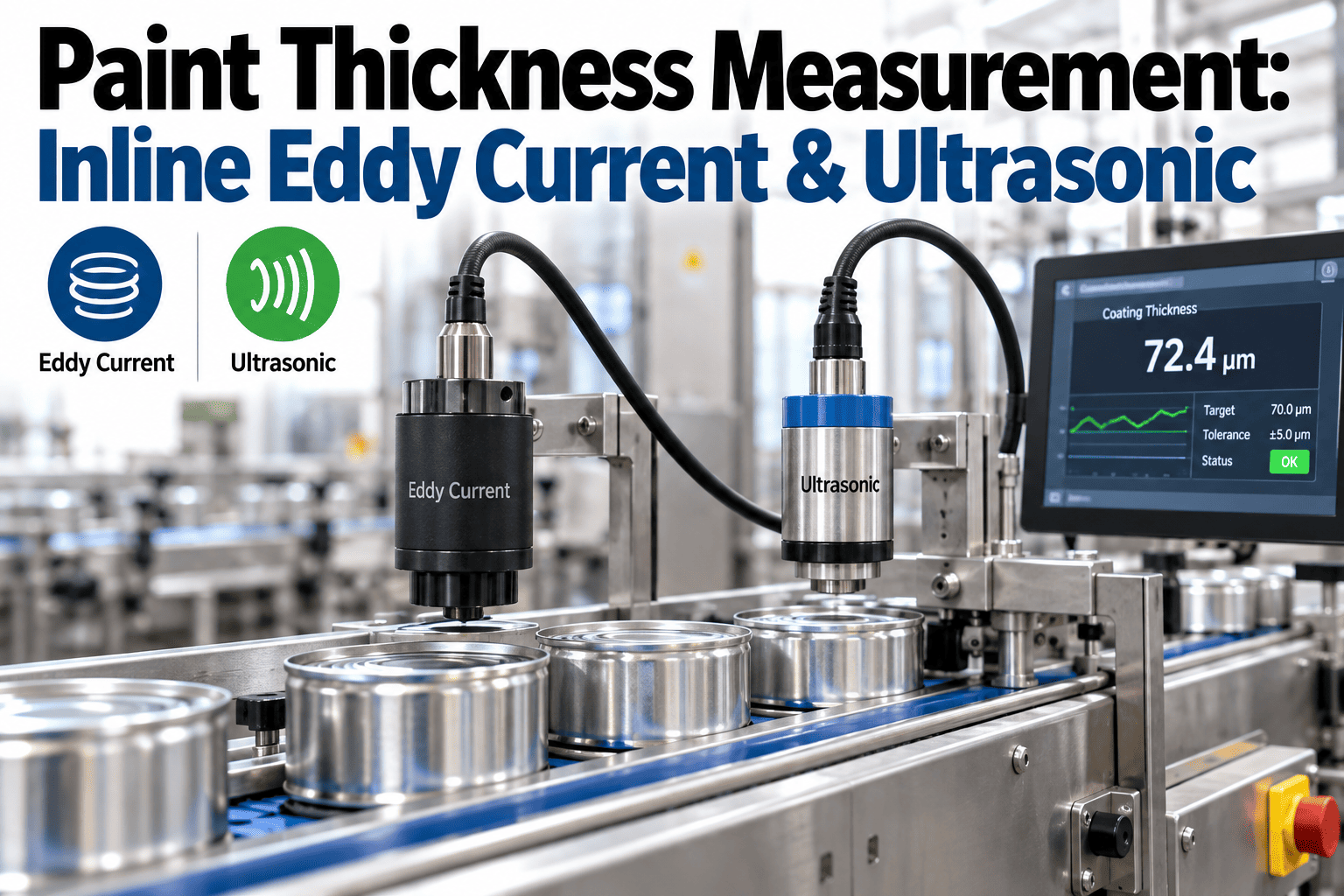
Inline gauging changes the unit of measurement from "the shift" to "the panel." Non-contact eddy current and magnetic sensors integrated into the paint line measure film build continuously as bodies move through, capturing thickness at hundreds of points per body rather than a handful of manual spot checks per shift.
The Business Case for Continuous DFT Gauging
- Every panel measured in real time replaces a handful of manual spot checks per shift, eliminating blind spots between samples
- Thickness data correlated live against spray robot parameters isolates which pass, gun, or path is driving variation
- Material savings compound as gauging identifies overbuild zones that can be trimmed without risking corrosion protection
Request a Film Build Audit →
The Four Layers That Make Up Total Film Build
Total paint thickness is not one number — it is the sum of four distinct layers, each with its own target range and its own failure mode when it runs too thin or too thick. Inline gauging at its most useful separates these layers rather than reporting only a combined total.
Clearcoat
35-45 µm — UV protection and gloss retention
Basecoat
15-20 µm — color consistency and metallic flake orientation
Primer Surfacer
30-40 µm — chip resistance and surface leveling
E-Coat
18-25 µm — the primary corrosion protection layer
Handheld Spot Checks vs. Continuous Inline Gauging
| Decision Area |
Handheld Spot Checks |
Continuous Inline Gauging |
| Coverage |
A handful of fixed points checked per shift, assumed representative of the entire body. |
Hundreds of measurement points captured per body across every panel automatically. |
| Variation Visibility |
Within-body variation invisible; only shift averages are tracked over time. |
Panel-to-panel and zone-to-zone variation visible immediately, isolating problem areas. |
| Root Cause Speed |
Thickness deviation traced back to a spray pass hours or days after the fact, if at all. |
AI correlates thickness reading to robot path, atomization setting, and booth conditions in real time. |
| Material Usage |
Overbuild margins kept wide out of caution since verification is infrequent. |
Overbuild identified and trimmed safely once full-body variance is understood and controlled. |
| Warranty Traceability |
No panel-level thickness record exists to reference during a corrosion claim investigation. |
Every panel's thickness history logged and retrievable against any vehicle identification number. |
See live panel-by-panel film build maps configured for your body geometry
Book a Demo
Where Thickness Variance Concentrates Across a Body
Not every panel behaves the same way under a spray robot's path. Complex geometry, recessed areas, and edges consistently show more variance than flat panels, which is exactly why zone-level data matters more than a single body average.
Hood and Roof
Large flat panels typically hold the tightest tolerance, making them a useful baseline for detecting systemic drift.
Door Edges and Jambs
Complex angles and recessed geometry create the widest variance, often running thin where robot path coverage overlaps poorly.
Rocker Panels and Sills
Lower body zones are prone to underbuild from gun angle limitations, directly affecting corrosion resistance in the highest-exposure area.
Fenders and Quarter Panels
Curved transitions often show overbuild as robots compensate for angle change, representing recoverable material savings.
Deployment Timeline: From First Sensor to Full-Body Correlation
Week 1-2
Non-contact eddy current sensors installed at line speed measurement stations
Gauging stations positioned post-cure to capture final film build without disrupting existing paint line throughput.
Week 3-4
Live thickness maps active for every body passing the station
Panel-level dashboards visible to quality engineers, with historical variance data building against baseline.
Week 5-8
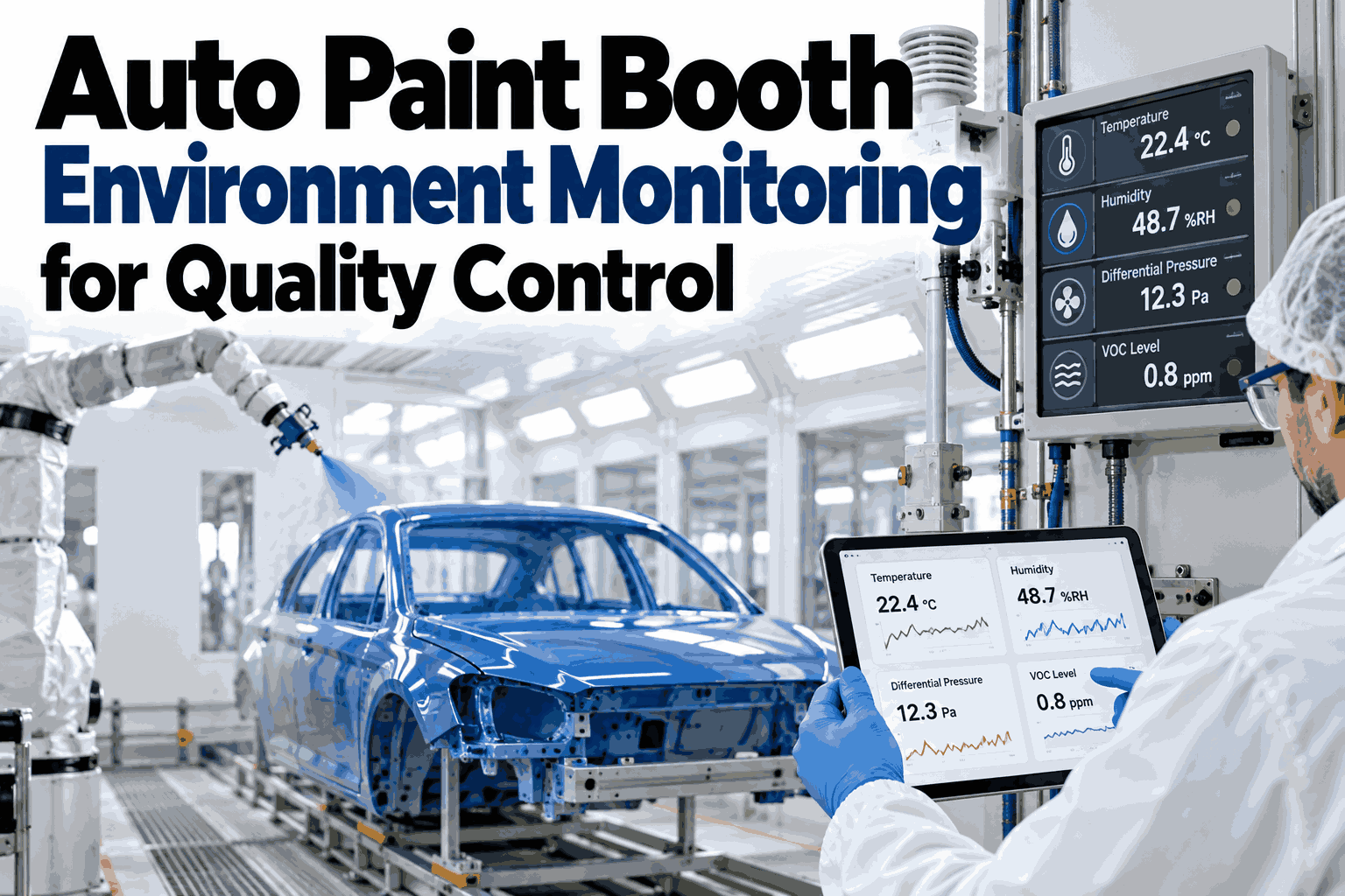
AI correlates thickness variance against spray robot and booth parameters
Root cause models validated against known defect events, isolating which process variables drive which variance patterns.
Month 3-6
Material optimization recommendations active across the full body
Overbuild zones trimmed safely, underbuild zones corrected, with documented material savings and improved corrosion consistency.
Frequently Asked Questions
Does inline gauging work on both metallic and solid color finishes?
Yes. Eddy current and magnetic induction gauging methods work across coating types, though the underlying substrate and layer composition determine which sensing method is optimal. Metallic basecoats with aluminum flake require slightly different calibration than solid colors, and our engineering team configures sensor settings specific to your paint system during commissioning. This ensures accuracy is maintained regardless of the finish being measured.
Can this replace our handheld DFT probes entirely?
Most plants keep handheld probes as a calibration reference and for ad hoc spot verification, while the inline system becomes the primary source of continuous data. The two methods complement each other well since inline gauging covers volume and consistency while handheld probes remain useful for targeted investigation. Details on integrating both into a single quality workflow are available through
iFactory support.
How accurate is inline gauging compared to a calibrated handheld probe?
Properly installed and calibrated inline sensors achieve accuracy comparable to handheld probes, typically within a few microns, while covering vastly more measurement points per body. Calibration is verified against certified reference standards during commissioning and re-verified on a scheduled basis to maintain measurement confidence over time.
Will this identify which specific spray robot is causing thickness variance?
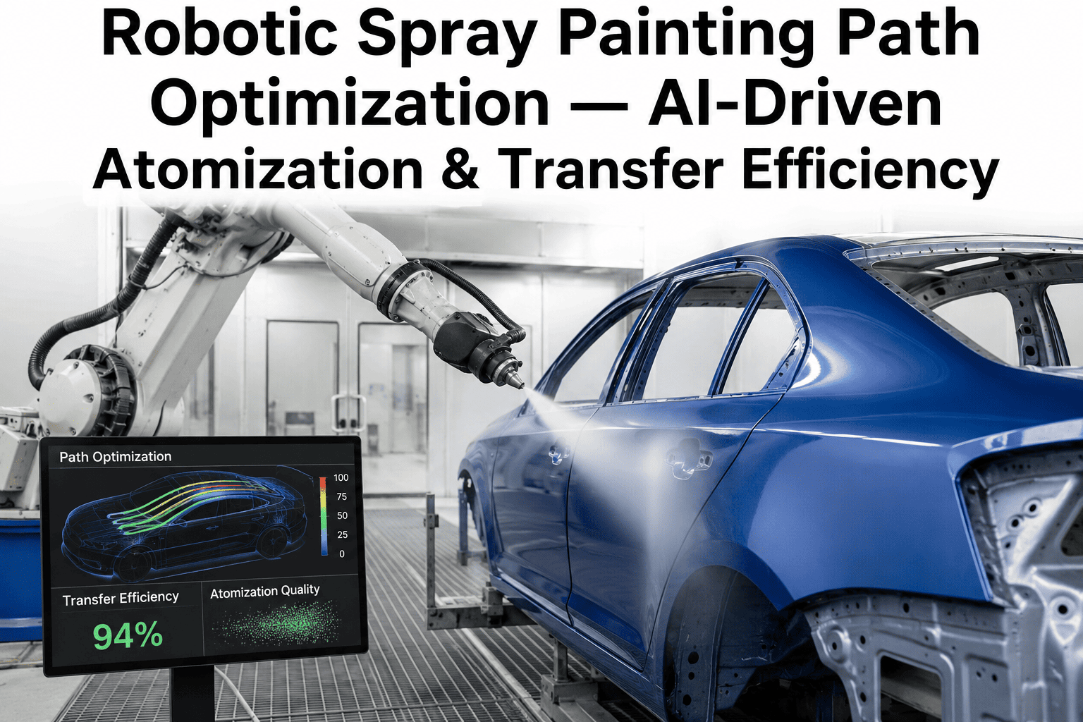
Yes, when thickness data is time-stamped and correlated against robot path logs, atomization settings, and booth zone identity, the AI model can isolate which robot, gun, or pass is contributing to a specific variance pattern. This turns a body-level thickness problem into an actionable, robot-specific correction rather than a vague quality trend.
How much material savings is realistic from this kind of programme?
Savings depend heavily on how much overbuild margin currently exists in your process, but plants moving from spot-check verification to full inline gauging commonly identify eight to fifteen percent in recoverable material cost once overbuild zones are confidently trimmed. Our team can model a savings estimate specific to your current film build data when you
book a working session.
Stop Averaging. Start Measuring Every Panel.
Your Paint Thickness Varies More Than Your Spot Checks Show. See the Real Picture.
iFactory's inline DFT gauging platform gives paint quality teams a full-body thickness map correlated against spray parameters in real time — catching material waste and corrosion risk that spot sampling never sees. Sensors live in weeks. First correlation validated within eight.
8-15%
Material savings potential