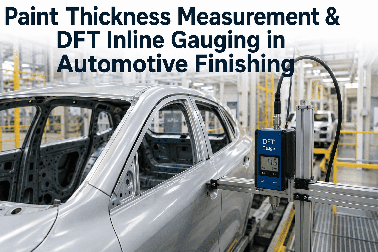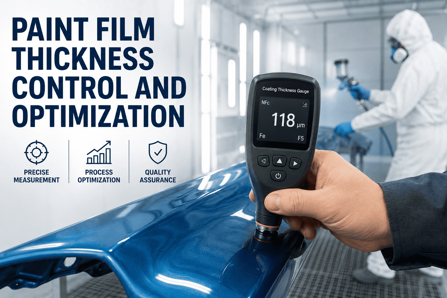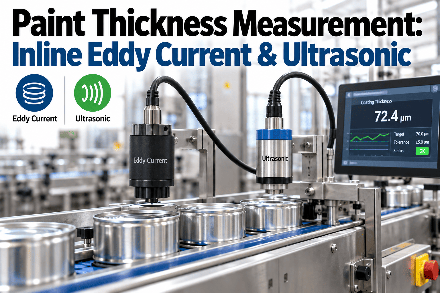
Every automotive body that leaves a paint shop carries a stack of coating layers measured in microns, and whether that stack lands inside specification decides corrosion life, appearance, warranty exposure and, increasingly, whether ADAS sensors behind painted bumpers see the road correctly. Paint thickness measurement is the discipline that verifies primer, basecoat and clearcoat against the coating specification before a body moves downstream — and the method you choose has to match the substrate under the paint, because steel, aluminium and plastic each demand a different physics. Getting the pairing wrong produces confident readings that are quietly false, which is why plants moving from spot checks to inline gauging usually start by talking through their layer stack with the iFactory support team before selecting sensors.
Measure Primer, Basecoat and Clearcoat Against Spec — Before the Body Moves On
iFactory pairs eddy current, magnetic induction and ultrasonic sensing to the substrate you actually run, then turns thousands of inline readings per body into a live compliance signal your quality team can act on in real time.
The Layer Stack You Are Actually Measuring
A modern automotive finish is not one coating but a sequence, each layer engineered for a job and each with its own thickness window. Read the stack from the metal up and the measurement problem becomes obvious: some layers are microns thin, some sit on steel and some on plastic, and a single number for the whole stack hides where a problem lives.
Ranges are representative of common OEM practice; every plant works to its own documented coating specification, and those windows are what an inline system checks each body against.
Three Sensing Methods, Matched to What Sits Under the Paint
There is no universal probe. The reliable rule is simple — match the method to the material — and the two most common causes of bad readings are the wrong tool for the substrate and poor surface condition. Here is how the three inline methods divide the work.
Coatings on Steel
Because steel is ferromagnetic, a magnetic-induction sensor reads non-magnetic paint over it directly and fast. It is the workhorse for conventional steel body panels and is governed by practices such as ASTM D7091 and ISO 2178.
Coatings on Aluminium
For non-ferrous conductive substrates like aluminium, an eddy current probe induces currents in the metal and reads coating thickness from the change in coil impedance. As bodies move to aluminium and mixed metals, this method becomes essential.
Coatings on Plastic
Bumpers, fascias and interior parts are non-metal, so electromagnetic methods do not apply. An ultrasonic pulse travels through the coating via couplant and reflects at each density interface, timing the echo to derive thickness — and can separate individual layers.
Aluminium hoods on steel bodies, plastic bumpers front and rear, and galvanised panels with a thin zinc layer all coexist on one vehicle. Combination probes that pair a phase-sensitive eddy current sensor with a magnetic-inductive sensor can measure the paint system and the zinc coating at once, auto-switching by substrate — which is exactly why a single-method deployment leaves gaps a real body will find.
See Your Own Layer Stack Mapped to the Right Sensors
Book a 30-minute walkthrough and we will map your primer, basecoat and clearcoat windows to a substrate-matched inline gauging plan — steel, aluminium, plastic and the mixed panels in between.
Spot Checks Versus Inline Gauging
Handheld probes have measured automotive paint for decades and still have their place. But a single reading tells you very little on its own — it only means something compared across points, panels and against a baseline. Inline gauging changes the economics of that comparison by covering vastly more points per body, automatically.
Properly installed and calibrated inline sensors reach accuracy comparable to handheld probes — within a few microns — while measuring far more of each body. The point of inline is not that it is more accurate per reading; it is that full coverage plus time-stamped history turns a vague quality trend into an actionable, robot-specific correction.
Reading the Specification: Where a Body Passes or Fails
A coating specification is not a single target but a window with a floor and a ceiling, and both edges cost money when crossed. Under-build risks corrosion and appearance defects; over-build wastes paint and can push ADAS-critical bumper zones out of tolerance. Inline gauging judges each reading against the window rather than a single nominal value.
| Layer | Representative Window | Primary Risk If Under | Primary Risk If Over |
|---|---|---|---|
| E-coat | 18–22 µm | Corrosion breakthrough in cavities | Material cost, cure load |
| Primer | 25–40 µm | Poor chip resistance, colour bleed | Sags, appearance defects |
| Basecoat | 10–25 µm | Incomplete colour hide | Metallic mottling, waste |
| Clearcoat | 35–50 µm | Reduced UV and etch protection | Wasted clear, ADAS bumper drift |
| Total System | 100–180 µm | Warranty and corrosion exposure | Paint overspend across every body |
Windows shown are representative of common OEM finishes; your own specification governs, and iFactory evaluates each layer against the numbers you supply.
How Inline Gauging Fits the Paint Line
The value of inline measurement comes from placing stations where the data means something and wiring the output back into decisions. A workable deployment follows a clear sequence rather than bolting a sensor onto a random spot on the conveyor.
Station Placement Post-Cure
Gauging stations sit after cure to capture final film build without disrupting existing line throughput, reading the coating in its finished, cross-linked state.
Substrate-Aware Sensing
Each station applies the method that matches the panel underneath — induction on steel, eddy current on aluminium, ultrasonic on plastic — so every reading rests on correct physics.
VIN-Level Data Capture
Readings are tied to the vehicle identifier and time-stamped, building a per-body record that supports audits and links thickness to the exact process conditions that produced it.
Variance Correlation to Robots
Thickness data is correlated against robot path logs, atomisation settings and booth zone, isolating which robot, gun or pass drives a variance pattern.
Closed-Loop Correction
Overbuild zones are trimmed safely and underbuild zones corrected, with documented material savings and more consistent corrosion protection body to body.
The iFactory AI Layer on Top of the Sensors
Sensors produce numbers; the payoff is what happens to those numbers. iFactory's AI turns a stream of inline thickness readings into panel-level intelligence — flagging drift before it becomes scrap and pointing engineers at the cause rather than the symptom.
Panel-Level Dashboards
Quality engineers see thickness by panel and zone with historical variance tracked against a baseline, so a slow drift is visible long before it trips a spec limit.
Robot-Specific Root Cause
When a variance pattern appears, the model isolates the contributing robot, gun or pass instead of leaving the team to guess across the whole booth.
Overbuild Recovery
Curved transitions where robots overcompensate for angle change show recoverable overbuild — the model quantifies the margin so it can be trimmed with confidence.
Validated Against Real Defects
Root-cause models are checked against known defect events, so the variables the system blames are the ones that actually drive the defect on your line.
The AI arrives pre-configured on an NVIDIA server that ships racked and ready with software pre-loaded — rack it, connect power and Ethernet, and the analytics layer is live. Scope covers cabling, network, PLC and SCADA integration, operator training and 24×7 remote monitoring, so your paint team gets a working thickness-intelligence system rather than a parts list.
Calibration and Verification Keep the Numbers Honest
An inline reading is only as trustworthy as the last time the gauge was proven against a known standard. Standards practice separates three steps that often get blurred, and skipping any of them lets a station drift into confident error.
A controlled, documented process against traceable standards across the gauge's operating range, restoring it to its stated accuracy — done by the maker or an accredited lab.
Routine checks against certified reference shims to confirm the gauge still reads within tolerance during production, at a defined frequency rather than once at install.
Aligning the gauge to a known thickness on the actual substrate when verification shows drift, so readings track the material the line really runs.
Why the ADAS Era Raised the Stakes
Paint thickness used to be a corrosion and appearance question. It is now also a safety question. As radar and camera sensors moved behind painted bumpers and fascias, coating thickness outside the manufacturer's window can degrade a sensor's ability to perform — which means a plastic bumper's paint stack is no longer a cosmetic detail but a functional tolerance that inline ultrasonic gauging exists to hold.
Frequently Asked Questions
Which measurement method should we use for our paint line?
It depends on the substrate under the paint, not the paint itself. Use magnetic induction for coatings on steel, eddy current for coatings on aluminium and other non-ferrous conductive metals, and ultrasonic for coatings on plastic bumpers, fascias and other non-metal parts. Mixed-material bodies usually need more than one method, which is why combination probes and multi-station inline layouts exist. Our team can map your specific panel mix to the right sensing plan — reach out to iFactory support to walk through it.
Can inline sensors separate primer, basecoat and clearcoat, or just total thickness?
It varies by method. Magnetic and eddy current gauges read the total non-conductive coating over the metal as one figure, while advanced ultrasonic gauges can distinguish individual layers because each coating interface reflects the pulse differently. Clearcoat in particular is acoustically distinct and separates cleanly, whereas multiple basecoat passes can be harder to resolve. Where individual-layer control matters — as it increasingly does for ADAS bumper zones — the method and sensor are selected specifically to deliver per-layer numbers rather than a single stack total.
How accurate is inline gauging compared with a handheld probe?
Properly installed and calibrated inline sensors achieve accuracy comparable to handheld probes, typically within a few microns, while covering far more measurement points per body than any manual check can. The real difference is coverage and traceability rather than per-reading accuracy: inline stations read every body at line speed and time-stamp every value, so the data supports both compliance records and robot-level root cause. Accuracy is held over time by verifying against certified reference standards on a scheduled basis after commissioning.
Will this tell us which spray robot is causing a thickness problem?
Yes, when thickness data is time-stamped and correlated against robot path logs, atomisation settings and booth zone identity, the model can isolate which robot, gun or pass is contributing to a variance pattern. That turns a body-level thickness issue into an actionable, robot-specific correction instead of a vague quality trend. Curved transitions frequently show overbuild where robots compensate for angle change, and those zones often represent recoverable material savings once they are identified. Book a demo to see the correlation view on a line like yours.
What material savings are realistic from moving to full inline gauging?
Savings depend heavily on how much overbuild margin currently exists in your process, so there is no universal figure. Plants moving from spot-check verification to full inline gauging typically find recoverable margin concentrated in curved transitions and edges where robots overspray to guarantee coverage. Once those zones are quantified against the specification floor, overbuild can be trimmed safely while underbuild is corrected, with the savings documented body to body. The economics improve further because the same data tightens corrosion consistency, reducing rework alongside paint spend.
Turn Coating Thickness From a Spot Check Into a Live Compliance Signal
iFactory pairs substrate-matched inline sensing with an AI layer that verifies every layer against your specification, catches drift before it becomes scrap, and points engineers at the robot behind a variance. Book a walkthrough to see it on a paint line running today.