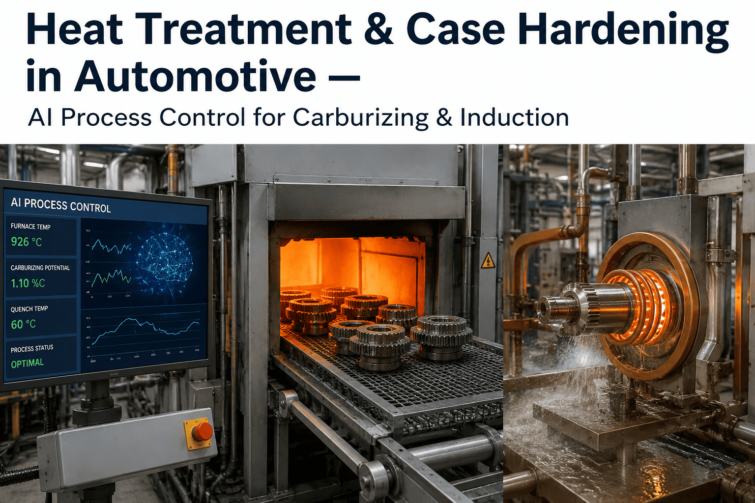
A gear line process engineer once traced a torsional fatigue failure back through six months of production records before finding it: a furnace atmosphere drift of a few tenths of a percent carbon potential, sustained for three shifts before anyone noticed the case depth on the affected batch had crept outside specification. Case depth, surface hardness, and residual stress are the three variables that decide whether a carburized gear survives its design life or fails early in the field, and all three are set inside a furnace or induction coil where the process engineer cannot see them directly. AI-driven process control changes that by turning furnace atmosphere, quench rate, and coil power into continuously monitored, tightly controlled variables instead of settings checked once per shift on a paper log.
Heat Treatment & Case Hardening — AI Process Control for Carburizing and Induction Hardening
AI-powered process control monitors furnace atmosphere, quench rate, and induction coil power in real time — holding case depth and surface hardness inside specification on every part instead of catching a drift after a batch has already shipped.
Carburizing vs Induction Hardening — Different Physics, Different Control Points
Carburizing diffuses carbon into the surface of a steel part at austenitizing temperature, then quenches to form a martensitic case — producing a gradual hardness profile controlled by carbon diffusion. Induction hardening rapidly heats the surface with a high-frequency alternating magnetic field, then quenches, producing a sharper hardness profile controlled by heat conduction rather than chemistry. A process engineer choosing between them is choosing which physics — diffusion time or conduction depth — becomes the control point that AI monitoring needs to hold steady.
Where Case Depth Actually Goes Wrong on the Production Floor
Effective case depth is typically defined against a specific hardness value — often expressed as depth to 50 HRC for a carburized and quenched part — and specifications commonly require a carburized case depth between 0.2 mm and 1.2 mm with a core hardness between 250 and 450 HV, depending on the component. Outside that window, impact fracture strength for a high-load part like a constant velocity joint or gear cannot be consistently guaranteed. The variables that push case depth outside that window are rarely dramatic: a furnace carbon potential that drifts by a few tenths of a percent, a hardening temperature that creeps a few degrees below the 800°C to 870°C window common for CVJ carburizing, or a quench that is slightly slack on one rack position relative to another.
Constant velocity joint components can carry over 35 metallurgical inspection points and 25 dimensional inspection points on a single part — reflecting how tightly modern automotive specifications now define case depth at multiple locations, not just a single surface reading. That inspection burden exists precisely because furnace and coil process variables are hard to hold steady across a full production shift without continuous monitoring, and a batch that passes a spot check may still contain parts drifting toward the edge of tolerance.
Stop Finding Out About a Case Depth Drift After the Batch Has Shipped
See how continuous furnace atmosphere and induction coil monitoring keeps every part inside case depth and hardness specification, batch after batch.
Four Control Points From Furnace Load-In to Final Hardness Check
The Hidden Variable Combined Carburizing and Induction Processes Are Trying to Control
Some gear and shaft programs combine carburizing with a subsequent induction hardening pass, aiming for the fatigue performance benefit of a deeper, dual-mechanism case. Research on combined processing found that the deepest combined case — carburized to 1.5 mm and induction hardened to 3.0 mm — did not automatically produce the best torsional fatigue life, with tensile residual stress at the case-core interface identified as the likely reason non-induction-hardened samples sometimes outperformed expectations. This is exactly the kind of subtlety that a single hardness reading cannot reveal, and that only continuous parameter tracking across many production batches can correlate back to a root cause.
How Process Engineers Choose Between Carburizing, Induction, and Nitriding
Selecting a hardening process is rarely about hardness alone. Case depth requirements, masking needs for selective hardening, corrosion sensitivity, and production volume all weigh into the decision, and monitoring data from the current process is often the best evidence for whether a change is justified.
| Factor | Carburizing | Induction Hardening | Nitriding |
|---|---|---|---|
| Typical case depth | 0.2–1.5 mm | Over 1 mm, part-dependent | Shallow, sub-millimeter |
| Selective masking | Straightforward | Coil-geometry dependent | Straightforward |
| Production throughput | Batch parallel processing | Piece-by-piece | Batch parallel processing |
| Corrosion sensitivity | Added carbon can increase sensitivity | No added surface chemistry | Improved surface resistance |
| Repeatability driver | Furnace atmosphere control | Coil frequency and power control | Furnace atmosphere control |
Questions Process Engineers Ask About AI Heat Treatment Process Control
Hold Case Depth Inside Specification on Every Part, Every Batch
Continuous furnace atmosphere, quench, and induction coil monitoring — catching a drift before it becomes a fatigue failure in the field.