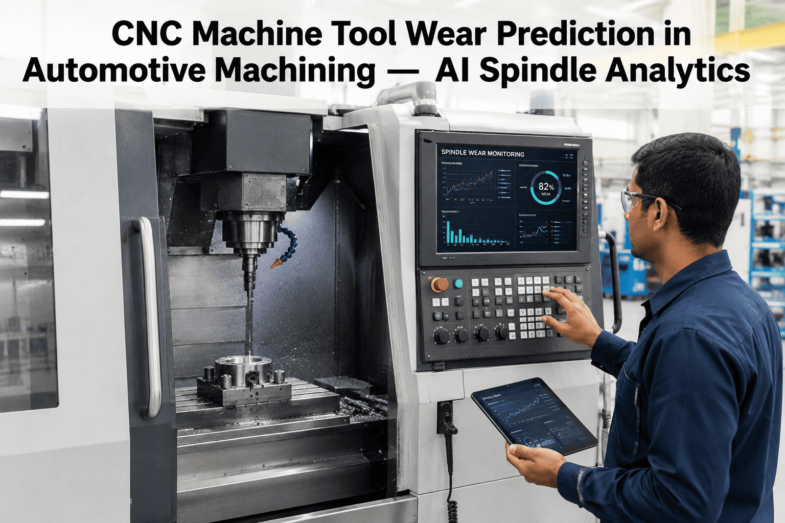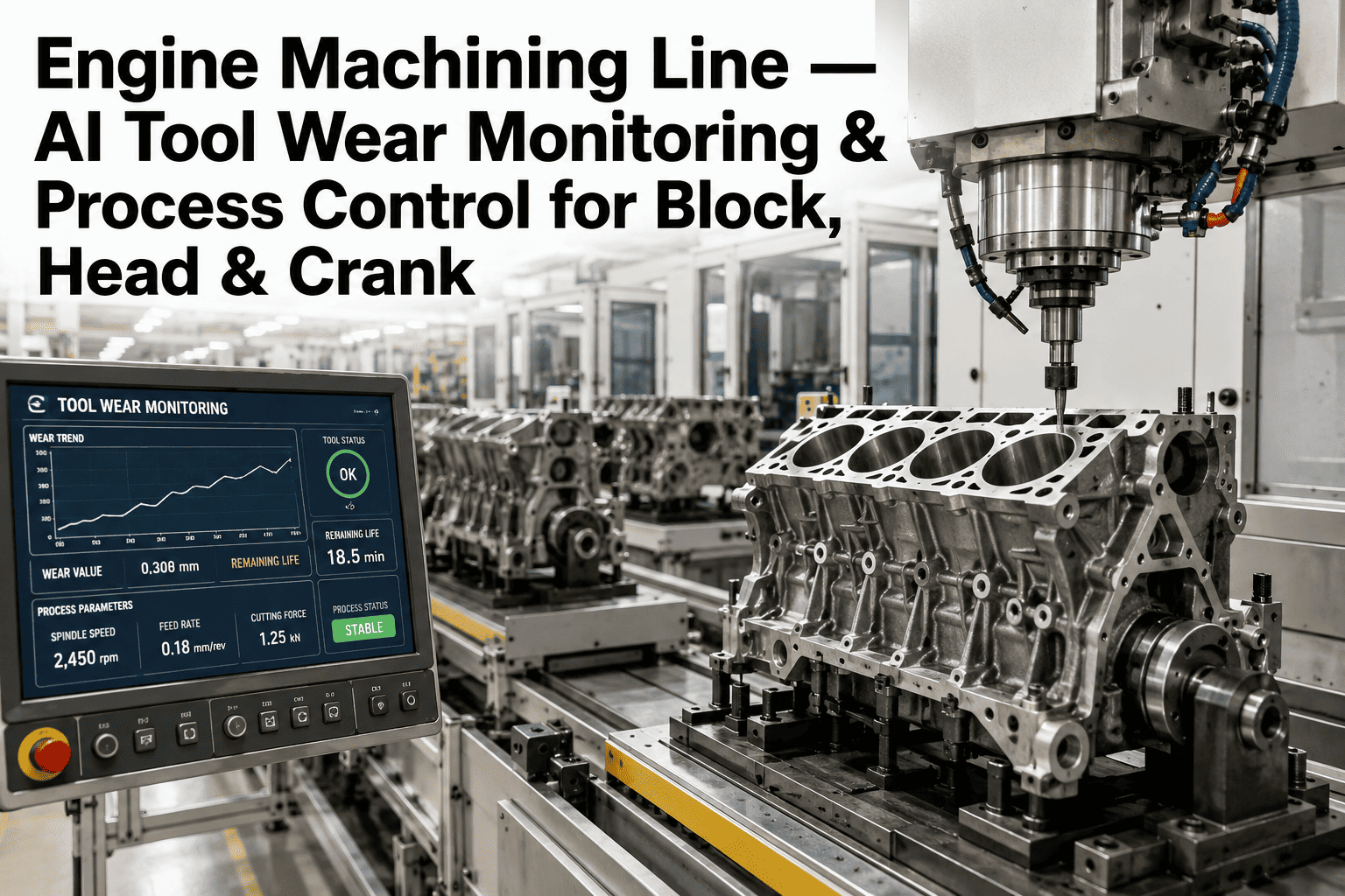
A worn cutting insert rarely fails all at once. It degrades through a predictable sequence of flank wear, built-up edge, and thermal softening long before it snaps or scores a bore, and every stage of that sequence leaves a signature in spindle load, vibration, and acoustic emission data that a CNC controller already captures but rarely interprets. Engine machining lines running block, head, and crankshaft operations at automotive volume cannot afford to treat tool replacement as a fixed-interval guess, because a single missed wear transition can scrap dozens of high-value castings before an operator notices a surface finish problem. Book a demo to see how iFactory turns existing machine signals into an early tool wear warning system.
Catch Insert Wear and Spindle Degradation Before They Become Scrapped Blocks, Heads, or Cranks
iFactory monitors spindle torque, vibration, and acoustic signals across your engine machining line in real time, flagging tool wear transitions and surface finish risk before a part leaves the fixture out of tolerance.
Fixed-Interval Tool Changes Waste Good Tool Life and Still Miss Failures
Most engine machining lines still schedule insert and tool changes on a fixed cycle count, set conservatively enough to avoid catastrophic failure but rarely tuned to the actual wear rate of a specific tool, material batch, or spindle. This approach fails in both directions at once. Tools pulled early waste a meaningful percentage of their remaining useful cutting life, adding avoidable tooling cost across a high-volume line running thousands of cycles per shift. Tools that degrade faster than the schedule assumes, because of a harder casting batch or a coolant flow variance, can still produce out-of-tolerance bores or surface finish defects between scheduled changes, and those defects are often not caught until final inspection or, worse, an end-of-line leak test.
Current tool condition monitoring research shows that AI models analyzing spindle torque, vibration, and acoustic emission signals can identify the specific stage of tool degradation, including flank wear, built-up edge, and fracture risk, using signals the CNC controller already generates without additional hardware in many physics-hybrid approaches. This shifts the underlying decision from a calendar-based guess to a condition-based judgment tied to the tool's actual state, which is the same principle that separates reactive from world-class maintenance performance across every other category of rotating and cutting equipment on the floor.
The economics compound quickly across a high-volume engine plant running multiple shifts. A line producing several thousand blocks or heads per week, even with a modest reduction in premature tool changes and a modest reduction in wear-related scrap, recovers meaningful tooling budget and machine uptime within a single quarter, and the recovered capacity often matters as much as the direct cost savings when a plant is running near its production ceiling to meet program volume commitments.
Four Signal Types Feed Most AI Tool Wear Monitoring Systems
Where Tool Wear Risk Concentrates Across Block, Head, and Crankshaft Operations
Tool wear does not behave identically across every station on an engine machining line. Each major component operation carries a distinct dominant failure mode, and an effective monitoring program tunes its sensitivity and alert thresholds to the specific risk at each station rather than applying one generic wear model line-wide.
The Four Stages an AI Model Needs to Distinguish to Be Useful on the Floor
A tool wear monitoring system is only as valuable as its ability to distinguish between wear stages that require different actions. A model that only flags "wear detected" without stage classification forces the same conservative response every time, which defeats much of the purpose of moving beyond a fixed-interval schedule in the first place.
Why the Quality of Your Training Dataset Matters More Than the Model Architecture
Plants evaluating AI tool wear monitoring often focus their diligence on the underlying model architecture, comparing convolutional neural networks against transformer-based approaches or physics-hybrid regression models. In practice, the dataset feeding whichever model is chosen matters far more to real-world accuracy than the architecture itself. A model trained exclusively on a single casting hardness range, a single coolant formulation, or a single spindle's baseline vibration signature will misclassify wear stages the moment production conditions shift even slightly, which happens routinely across shifts, material lots, and seasonal humidity changes that affect coolant viscosity.
A reliable training dataset for engine machining tool wear needs three characteristics: coverage across the actual range of material batches and cutting parameters the line runs in normal production, ground-truth labels correlated against verified inspection and scrap outcomes rather than assumed wear curves, and enough volume across each wear stage, particularly the rarer failure and fracture events, to avoid a model that is only confident about the common middle stages of wear and uncertain about the stages that matter most operationally. Plants that skip the labeling step and rely purely on unsupervised anomaly detection often get a system that reliably flags "something changed" without the stage-level specificity that lets an operator decide whether to finish the current run or stop immediately.
A Four-Phase Path From Single-Machine Pilot to Full Line Coverage
What Undetected Tool Wear Actually Costs an Engine Machining Line
The financial case for AI-based wear monitoring is rarely about the tooling budget alone. The larger cost sits in scrapped castings, rework, and the downstream inspection and warranty exposure created when a worn tool produces an out-of-tolerance bore or a marginal surface finish that passes visual inspection but fails in the field.
Three Realistic Starting Points Depending on Existing Instrumentation
Not every plant needs a full sensor retrofit to get meaningful value from tool wear monitoring, and a phased investment approach lets a VP Operations or process engineering team prove value before committing to plant-wide hardware spend. The table below outlines three realistic starting tiers based on the instrumentation a line already has in place.
| Tier | Instrumentation Used | Best Fit |
|---|---|---|
| Controller-Only | Existing spindle torque and feed load signals | Fast pilot, lowest upfront cost |
| Vibration-Augmented | Controller data plus retrofit accelerometers | Lines with prior chatter or fracture history |
| Full Sensor Suite | Controller, vibration, acoustic emission, and vision | High-value stations like block boring and crank grinding |
Most plants find the fastest path to a defensible business case is starting at the controller-only tier on a single high-value station, proving the stage-classification accuracy against known scrap history, and using that validated result to justify the sensor investment needed for the next tier rather than committing to full instrumentation across the line before any results exist.
Four Reasons AI Tool Wear Programs Stall After a Promising Pilot
Tool wear monitoring pilots frequently show strong results on a single machine and then fail to scale across the full engine machining line. These four patterns explain most of the stalls.
The Same Wear Data Serves Process Engineers, Quality, and Tooling Purchasing Differently
A process engineer reads tool wear data primarily to validate cutting parameters, using stage-transition timing to confirm whether a recent feed rate or coolant change extended or shortened effective tool life. This is often the fastest way to catch a process drift before it shows up as a scrap trend, since a tool wearing faster than its historical baseline is frequently an early symptom of a parameter or material issue rather than a tooling defect on its own.
A quality manager uses the same data to build a defensible link between a specific out-of-tolerance part and the exact tool condition at the time it was produced, which matters directly for containment and customer notification decisions when a defect is discovered downstream. Tooling purchasing and plant finance use the aggregated wear and replacement data differently again, tracking actual versus budgeted tool consumption to right-size purchasing agreements and identify which insert grades or suppliers deliver the most usable life per dollar under real production conditions rather than vendor-quoted averages. Sharing one consistent wear dataset across these three functions avoids the common situation where purchasing negotiates a tooling contract based on assumptions that neither engineering nor quality can actually confirm from the floor.
Common Questions About AI Tool Wear Monitoring in Engine Machining
Does AI tool wear monitoring require new sensors on every machine, or can it use existing CNC controller data?
It depends on the level of precision required and the specific failure modes a plant is most concerned about. Physics-hybrid models that combine classical wear equations with data-driven regression on existing CNC internal signals, such as spindle torque and feed load, can produce meaningful remaining useful life estimates without any additional hardware beyond the controller itself. For plants prioritizing early detection of sudden events like chipping or fracture, adding affordable accelerometer or acoustic emission sensors substantially improves detection speed and reliability, since these events often show up in vibration and acoustic signatures before they meaningfully shift spindle torque. Book a demo to see which approach fits your current machine instrumentation.
How accurate are current AI tool wear prediction models compared to manual inspection?
Recent published research on hybrid physics-informed machine learning models for milling and turning operations reports force prediction accuracy exceeding 98 percent and tool wear estimation accuracy exceeding 95 percent, with the physics-informed approach improving wear prediction accuracy by more than 16 percent compared to purely data-driven machine learning alone. These figures come from controlled research settings and real production accuracy depends heavily on the quality and volume of training data collected from your specific machines, materials, and cutting parameters, which is why a calibration period against your own historical scrap and inspection data matters before fully trusting the model's stage classifications. Contact support to discuss a calibration approach for your specific machining line.
Can the same tool wear model work across block, head, and crankshaft operations, or does each station need its own model?
Each station generally needs its own tuned model, even when the underlying AI architecture is shared across the line. Block machining, cylinder head machining, and crankshaft machining involve different tool geometries, different dominant wear mechanisms, and different tolerance-critical outcomes, from bore roundness to valve seat flatness to journal surface hardness. A single generic wear model applied uniformly across all three stations tends to underperform station-specific models trained on the actual signal patterns and failure modes relevant to that operation. The shared value comes from a consistent monitoring platform and alerting workflow across stations, not from a single undifferentiated wear algorithm. Book a demo to see station-specific model configuration in practice.
What is the difference between tool wear prediction and tool breakage detection?
Tool wear prediction focuses on the gradual degradation of a cutting edge over its useful life, tracking flank wear, built-up edge, and thermal softening to estimate remaining useful life and recommend an optimal replacement window. Tool breakage detection is a faster, more reactive capability focused on identifying a sudden fracture or chip event within seconds so the machine can stop before it damages the workpiece, fixture, or spindle. A complete monitoring program needs both capabilities, since gradual wear prediction optimizes tooling cost and surface finish consistency, while breakage detection protects against the more acute and expensive failure mode of a snapped insert mid-cut. Contact support to review both detection layers for your line.
How long does it take to get a reliable tool wear model running on an existing engine machining line?
Most implementations follow a phased timeline rather than a single deployment event. An initial data collection phase, typically several weeks, establishes baseline signal patterns across normal tool life for the specific machines and materials in production. A calibration phase then correlates those signal patterns against known wear stages using historical scrap, rework, and inspection records, refining the model's stage classifications before it is trusted for live alerting. Most plants move from initial data collection to a functioning, alert-generating model within one to two production quarters, with accuracy continuing to improve as more production cycles feed the training dataset. Book a demo to see a realistic implementation timeline for your line.
Move Your Engine Machining Line From Fixed-Interval Guessing to Condition-Based Tool Changes
iFactory turns the signals your CNC controllers already generate into stage-level tool wear alerts, so block, head, and crankshaft operations catch degrading inserts before they scrap a casting or damage a fixture.