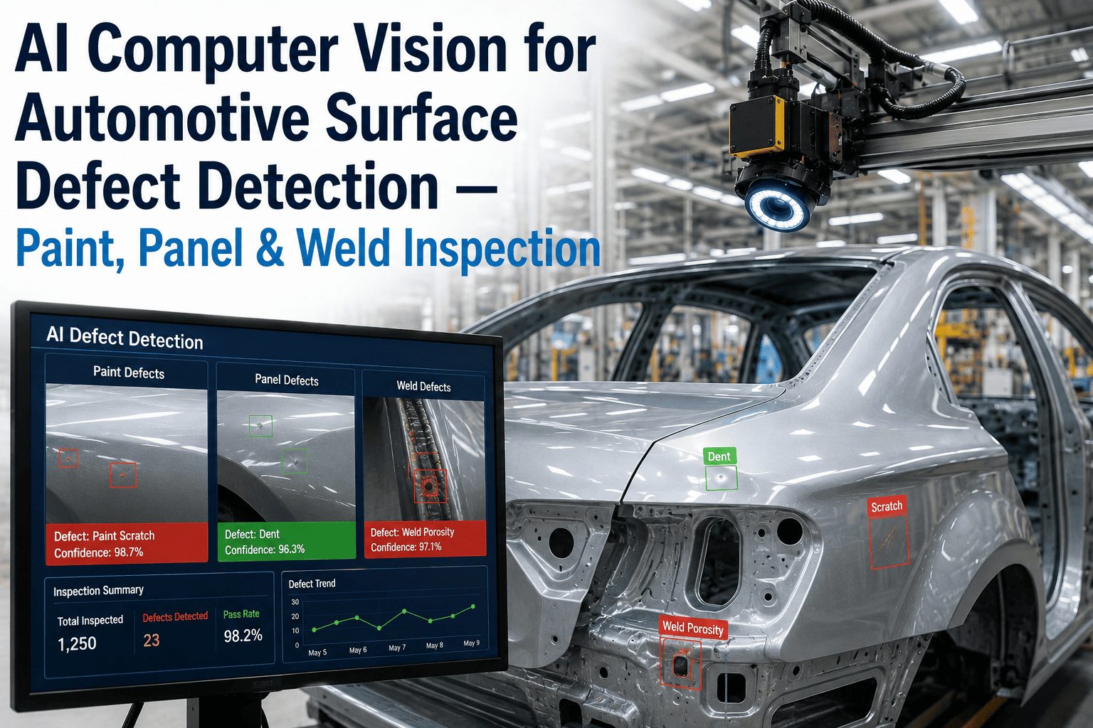
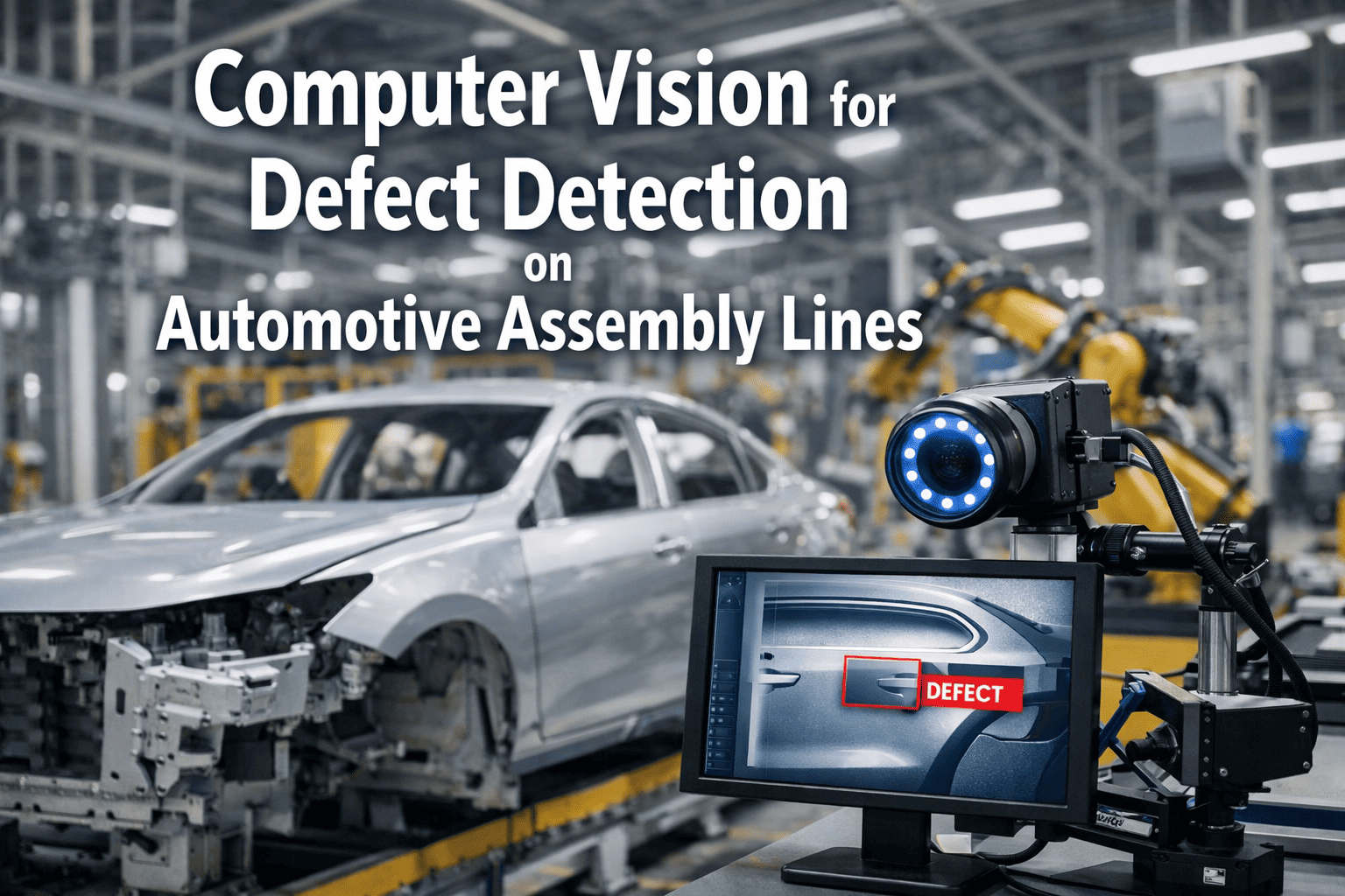
Porosity is one of the few weld defects that can sit invisibly inside a chassis or frame joint, pass a quick visual check and still weaken the part that carries the load. Automotive plants have three main ways to find it, which are radiography, ultrasonics and vision, and each sees a different slice of the problem. Artificial intelligence changes the job from a human squinting at grey images to a system that classifies every indication against your acceptance limits. This guide explains what each method can and cannot see, and you can explore how the combined approach would fit your inspection plan.
P1 AUTOMOTIVE WELD INSPECTION
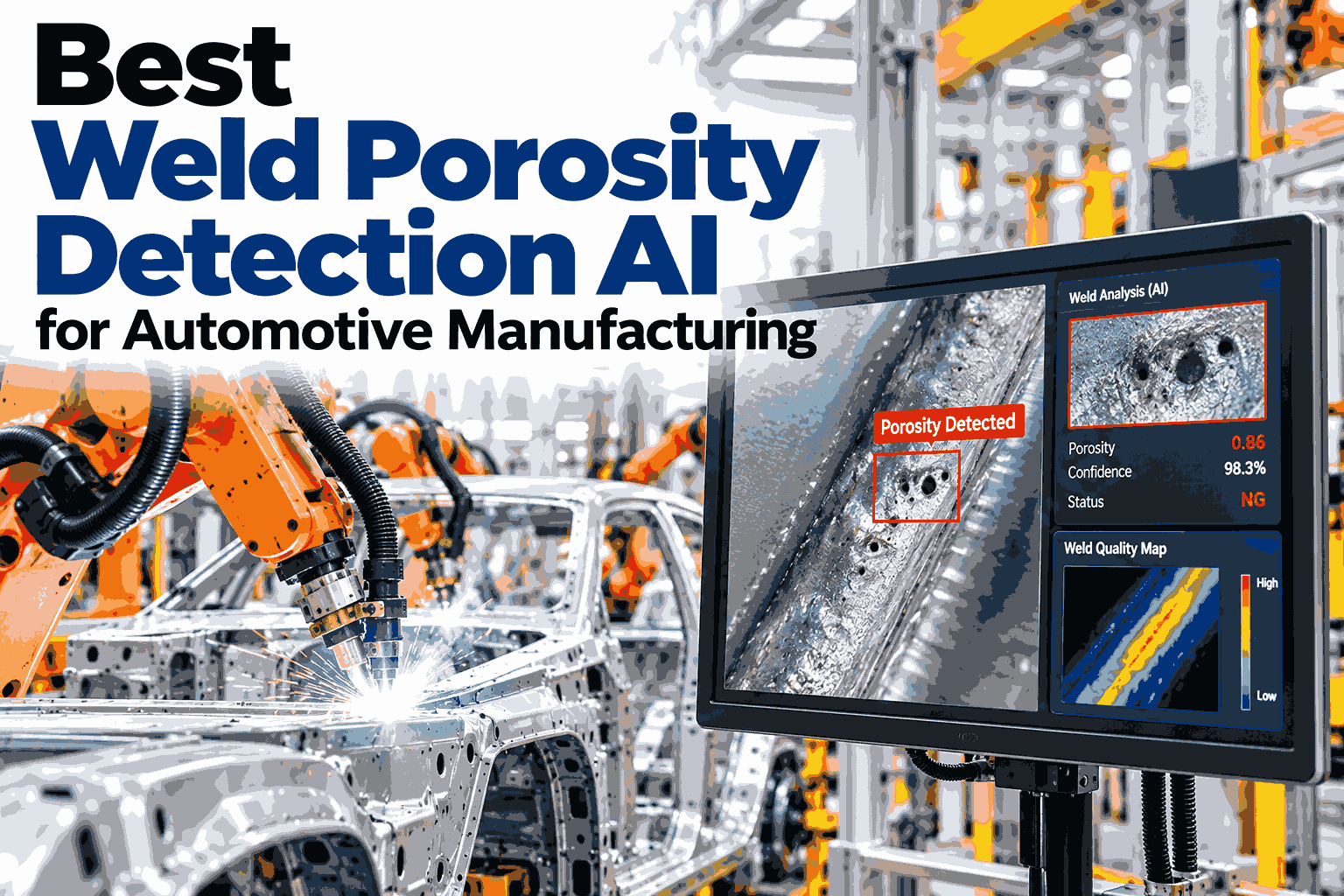
Best Weld Porosity Detection AI for Automotive Manufacturing
iFactory brings X-ray, ultrasonic and vision findings together with process data, so porosity in chassis, frame and structural welds is classified, ranked and traced.
WHERE IT MATTERS MOST
Not Every Weld Carries the Same Risk
Inspection effort should follow consequence, so the first step is ranking joints by what happens if they fail.
Tier 1
Crash and load-path structure
Joints that manage impact energy or primary loads justify the deepest inspection and the tightest limits.
Tier 2
Chassis, frame and suspension mounts
Fatigue-loaded joints where small internal voids can grow under repeated cycles.
Tier 3
Secondary brackets and closures
Lower consequence joints where lighter, faster checks are usually sufficient.
Tier definitions come from your own engineering and OEM requirements, and the AI applies whichever limits you assign to each tier.
KNOW YOUR ENEMY
The Four Faces of Weld Porosity
Pores differ in shape and distribution, and the pattern points toward the cause.
Scattered pores
Spread through the weld metal, often tied to weak or inconsistent shielding gas coverage.
Clustered pores
Grouped in one spot, commonly linked to a start, a stop or a short gas disturbance.
Linear pores
Aligned along the root or fusion line, often connected to contamination or joint preparation.
Surface blowholes
Break the surface and are the only kind that vision inspection can see directly.
DETECTION METHODS
What Each Method Actually Sees
No single method wins on every measure, which is why the strongest programs combine them.
Radiography (X-ray)
Internal visibility
Inline speed
Coverage of all parts
Ultrasonic testing
Internal visibility
Inline speed
Coverage of all parts
Vision inspection
Internal visibility
Inline speed
Coverage of all parts
The bars are illustrative relative comparisons, and real performance depends on joint type, material thickness and equipment.
Map the right method to each joint on your line
iFactory can walk through your weld types and show where radiography, ultrasonics, vision and process data each earn their place.
MATCHING METHOD TO JOINT
A Practical Decision Guide
The right choice depends on where the joint sits, how thick it is and how often it must be checked.
| Situation |
Best fit |
Why |
Watch out for |
| Every weld, every shift |
Vision plus process data |
Fast and continuous across all parts |
Cannot see internal pores directly |
| Thicker structural joints |
Ultrasonic or X-ray |
Can reveal volumetric voids inside the weld |
Setup and interpretation effort |
| Audit of a new process |
X-ray or CT sampling |
Provides detailed reference images |
Slow and limited to samples |
| Thin-gauge lap joints |
Process data plus targeted sampling |
Thin material limits ultrasonic resolution |
Needs strong process baselines |
SMART TRIAGE
The Inspection Funnel That Saves Time
AI works as a funnel, sending expensive inspection only to the welds that most need it.
Every weld produces process and vision data
Risk scoring flags suspect welds
Targeted X-ray or ultrasonic confirmation
Confirmed findings drive action
Confirmed results feed back to the model, so the funnel becomes more precise as it sees more of your parts.
INSIDE THE AI
How Indications Become Decisions
Raw images and signals are stacked through layers, and each one removes uncertainty before a verdict is made.
DecisionAccept, rework or hold against the assigned limit
ClassificationPore, inclusion or noise, with size and spacing
DetectionLocate indications in images and signals
DataImages, echoes, camera frames and arc data tied to the part
Each layer is tied to the serial number, so a decision can always be traced back to the evidence behind it.
ONE DEFECT, THREE VIEWS
What the AI Learns From Each Source
Each source teaches the system something different, and together they cover more than any one alone.
X-ray images
Separates dark pore shapes from image noise and fixture edges
Measures pore size and counts within a weld length
Builds a reference for what porosity looks like
Ultrasonic echoes
Recognizes echo patterns typical of gas voids
Tells volumetric flaws from geometry reflections
Tracks position along the weld path
Vision images
Finds surface blowholes and pits at line speed
Notes bead shape changes that hint at trouble
Links every result to the part serial number
LIMITS AND TRACEABILITY
Turning Findings Into Defensible Records
A detection is only useful if it can be judged against a rule and produced later during an audit.
Acceptance limitsSet from your OEM specification or a standard such as ISO 5817, per joint and quality level.
Evidence retentionImages, signals and verdicts stay attached to the part record.
Human reviewBorderline calls go to a qualified person, and the decision is recorded.
Root cause linkClusters map back to gas, surface or equipment conditions for correction.
EVALUATION SCORECARD
How to Judge a Porosity AI Platform
Ask for proof in each row below, because claims are easy and evidence is not.
| Question |
Strong answer |
Weak answer |
| Which methods does it support? |
Several methods combined into one record |
One method with no cross-check |
| How does it handle false calls? |
Tunable per joint, with review workflow |
One fixed sensitivity for everything |
| Can it show its evidence? |
Images and signals linked to each verdict |
A score with no supporting data |
| Does it connect to process data? |
Yes, so causes can be traced |
No, so findings stay isolated |
FREQUENTLY ASKED QUESTIONS
What Quality and NDT Teams Ask
Can vision alone detect internal porosity?
No, vision sees only what reaches the surface, so it catches blowholes but not voids buried in the weld. It is best used for fast coverage alongside process data and targeted internal checks.
See how the layers combine in a walkthrough.
Does AI replace qualified NDT personnel?
It supports them by screening images and signals and handling routine calls, while people still own borderline decisions and sign-off. That frees skilled staff to focus on the cases that need judgment.
Ask our support team how review workflows are set up.
How are acceptance limits applied?
Limits are configured per joint from your specification or chosen standard, so the AI measures indications against the rule you actually work to. Different tiers can carry different limits.
Review a limit configuration with our team.
Will it work on thin-gauge automotive joints?
Thin material limits some methods, especially ultrasonics, so these joints often rely more on process data and targeted sampling. The right mix is set joint by joint.
Contact support to discuss your specific joints.
What happens after porosity is detected?
The part is held or routed for rework according to your rules, and the pattern is linked to likely causes such as gas coverage or surface condition. Maintenance gets a specific task instead of a general complaint.
Walk through a sample case with us.
SEE INSIDE EVERY STRUCTURAL WELD
Find Porosity Before It Reaches the Road
iFactory unifies X-ray, ultrasonic, vision and process data to classify weld porosity and keep a traceable record for every safety-critical joint.